


o
o
o
t
o
o
I
I
o
a
O
I
a
o
I
I
o
t
I
o
a
o
O
o
I
o
o
o
I
o
o
I
o
o
o
a
o
I
a
o
o
o
o
o
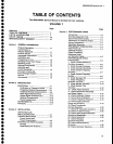
PREFACE
This
manual
contains
servic€
information
for
the
TEKTRONfX
494A1494Ap.
The information
is
tocated
in
two volumes.
Volume
1
contains
the
text and
Volume
2
contains
the
diagrams
and parts
lists.
The
Tabte
of
Contents
in
each
volume
lists
the
contents
of
both
volumes.
Manuals
that
describe
other
aspects
of
the
product
are:
.
Operator's
Manual
.
Operator's
Handbook
o
Programmer's
Manual
o
Programmer's
Reference
Guide
Who
Should
Use
This
Manual?
This
rnanual
is
intended
for
electronic
technicians
with
experience
in
servicing
digital,
analog,
and
rf circu-
itw.
Circuit
analysis
is
mostly
functionil
and
shoutd
help isolate
most
malfunctione
to
a
board
or
block
of
circuitry.
The
technician
should
then
be abte,
with
the
aid
of
test equipment,
to isolate
the malfunction
to
a
specific
component
or
components.
This
instrument
contains
firmware
that
provides
a
thorough instrument
check
during power
up
and
during
operation,
and
if
needed,
guides
the
usei
through
ai
abbreviated
front-panel
calibration
procedure.
lf
cali_
bration
cannot
be
achieved,
a
diagnostic
test
detects
and
isolates
most problems
to
the
system,
such
as
1st
LO. The
technician
can
then run
troubleshooting
diag-
nostics
to further
isolate
the
problem
to
the
board
or
block of
components.
Refer
to the
Maintenance
section
for
diagnostics
information.
Documentation
Standards
Most
terminology
and
graphics
follow
ANSI
stan_
qalds.
A
glossary
of
terms
is
provided
as
an
appendix.
Refer
to
the
following
standards:
494A/494AP
Service Vot.
1
.
ANSI
Y1.1
-
Abbreviations
.
ANSI Y32.2
-
Graphic
Symbots
o
IEEE
91
-
Logic
Symbots
Change/History
Inf
ormation
Sometimes
instrument
changes
occur
or
manual
errors
are
found
that
make
some of
the
information
in
the
manual
inaccurate.
When
that
happens,
Manual
Change
Information
notices
are inserted
at
the
rear
of
the
manual.
This helps
ensure
that the
manual
contains
the latest
and
most accurate
information
available
when
the
product
is sold.
History
information,
with
the
updated
data,
is
integrated
into
the text
or
diagrams:
When
a
text
page
is
updated,
the
revised pages
are
identified
by
a
revi-
sion
date in
the
lower
inside corner
of
the
page.
When
a
diagram
is
updated,
the revision
date is
placed
at
the
lower
center of
the
diagram. History
information
is
shown
with a
gray
tint. When a component
value
is
changed,
the
designator on
the drawing
is
boxed with
a
grey
outline.
When
a circuit
is
deleted
or
changed,
the
original
configuration
is
shown
in
grey,
drawn either
at
its
original
location
or
to the
side
of
the
drawing.
lf you
have a
manual
other
than
the
one
that
came
with your
instrument
it
may contain revisions
that do not
apply
to
your
instrument;
however
all
history
informa-
tion
that
pertains
to
the
earlier instruments
is retained.
When
a major modification
has
been made
to
an
assembly
or circuit
board, the
data
for
the
replaced
assernbly
will follow
the
new
information
and
will
be
identified
with appropriate
titles
or
headings such
as
instrurnent
serial
number range
or
the assembly
or
board
part
numbers.
Also, if your
instrument
has an
assembly replaced
with
a newer version,
documentation
for
the newer
assembly
may
be
supplied.
Contact
any
Tektronix
Ser-
vice
Center for information.