


o
o
o
a
o
o
o
a
a
a
o
o
o
o
a
o
o
o
a
o
o
o
o
o
a
o
O
o
o
o
o
o
O
o
o
o
o
o
o
o
o
o
o
o
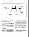
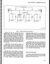
Theory
of
Operaton
-
4g4A/4g4Ap
Service,
Vol.
.l
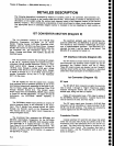
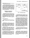
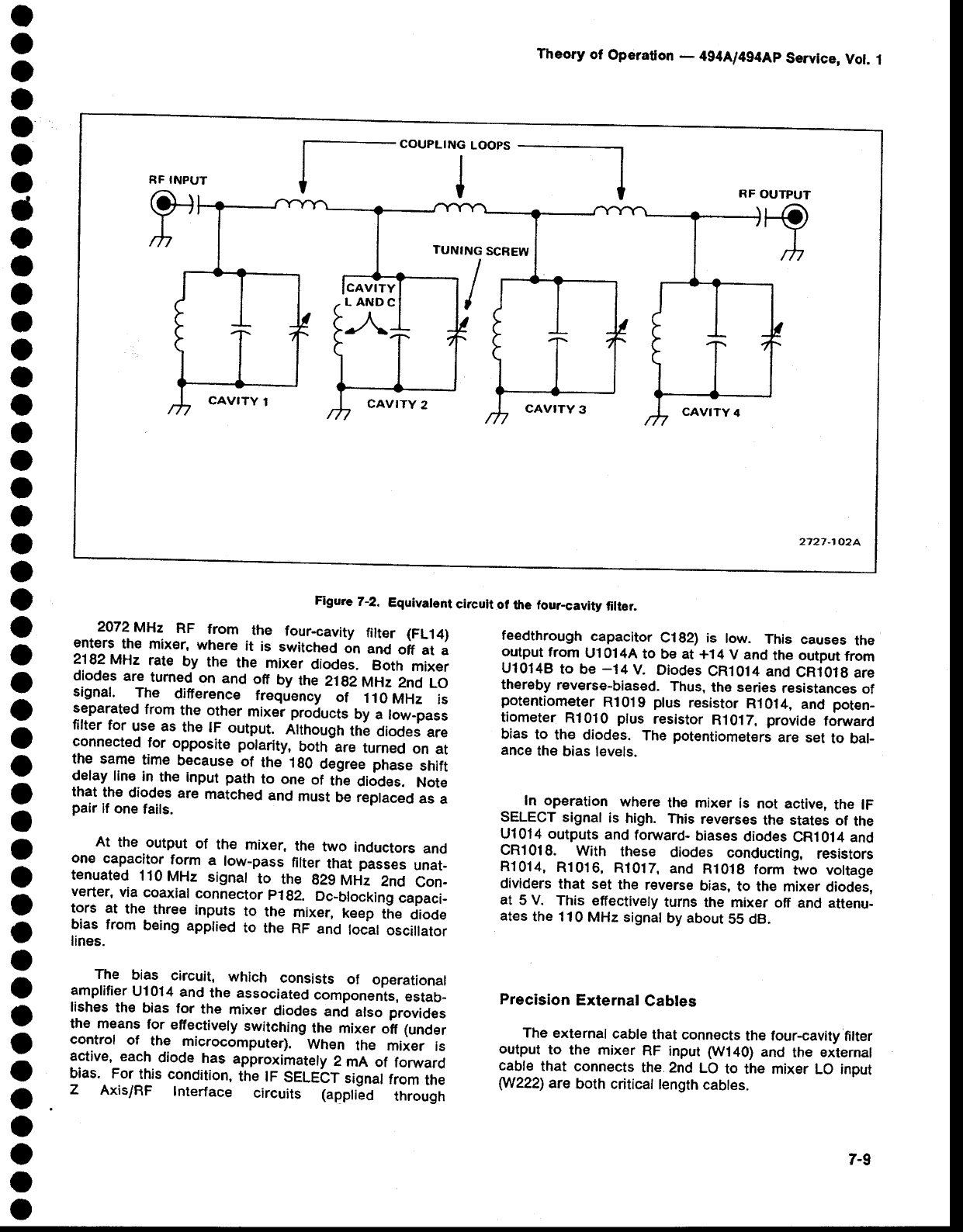
Figute
7-2.
Equivalent
circuit
of
the four-cavity
filter.
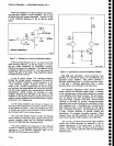
2072MHz
RF
from.the
four-cavity
fitter
(FL14)
enters
the
mixer,
where
it
is
switched
on
anO
off
at
a
2.182MH2
rate
by
the
the
mixer
diodes.
Both
mixer
diodes
are
tumed
on
and
off
by
the
2lg2
MHz
2nd
LO
signal.
The
difierence
frequency
of
110
MHz
is
separated
from
the other
mixer products
by
a low-pass
filter
for
use as
the
tF
output.
Attnougn
th!
diodes
are
connected
for
opposite
polarity,
both
are
tumed
on
at
the same
time
because
of
ths
1g0
degree phase
shift
delay.
line
in.
the input
path
to
one
of
t[e
diodes.
Note
that
the
diodes
are
matched
and
must
be
replaced
as
a
pair
lf one
fails.
At
the
output
of
the
mixer.
the
two
inductors
and
one
capacitor
form
a
low-pass
filter
that
passes
unat_
tenuated
110MHz
signat
to
the
g2gMtiz
2nd
Con-
verter,
via
coaxial
connector
plg2.
Dc_blocking
capaci-
tors
at
the
three
inputs
to
the
mixer,
keep
tne
diode
bias
from
being applied
to
the
RF
and
locat
oscillator
lines.
The
bias
circuit,
which
consists
of
operational
amplifier
Ul014
and
the associated
components,
estab-
lishes
th€
bias for
the
mixer
diodes
and
atso provides
the means
for
effectively
switching
thE mixer
oif
lunder
control
of
the
microcomputer).
When
the mixer
is
active,
each
diode
has
approximately
2
mA
of
forward
bias.
For
this
condition,
the tF
SELEbT
signal
from
the
Z
Axis/RF
lnterface
circuits
lappti-eO
through
feedthrough
capacitor
C182)
is
low.
This
causes
the
output
from
U1014A
to be
at +14
V and
the output
from
U10148
to
be
-14
V.
Diodes
CR1O14
and
CR101g
are
thereby
reverse-biased.
Thus,
the series
resistances
of
potentiometer
R101
9
plus
resistor
R1014,
and
poten_
tiometer
Rl010
plus
resistor
R1017,
provide
foruvard
bias
to
the
diodes.
The
potentiometers
are set
to bal-
ance
the
bias
levels.
In op€ration
where
the mixer
is
not
active,
the lF
SELECT
signal
is
high.
This
reverses
the
states
of
the
Ul0'14 outputs
and
foruvard-
biases
diodes
CRl014 and
CR1018.
With
these
diodes
conducting,
resistors
R1014,
R1016,
R1017,
and
R1018
form
two
voltage
dividers
that
set
the
reverse
bias,
to the
mixer
diodes.
at
5 V.
This
effectively
turns
the mixer
off
and attenu-
ates
the
110
MHz signal
by
about
55 dB.
Precision
External
Cabtes
The
external
cable
that
connects
the four-cavity
filter
output
to the
mixer
RF
input
(W140)
and
the
external
cable
that
connects
the 2nd
LO
to the mixer
LO input
W222)
are
both
criticat
tength
cabtes.
RF INPUT
Q+r
h
j--"ou"'-'T'oo"---l
RF
OUTPUT
+Fo
I
lh
TUNING
SCREW
I
,
CAVITY
1
CAVITY
2
CAVITY
3
CAV!TY
4
2727-1o2A
7-9