


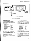
Instrument
Bus
Test
lf
the
microcomputer
performs
the
power-up
self-
test, but fails
to
properly
control
the
instrumeht,
the
instrument
bus interface may
be faulty.
Select
the
instrument
bus
test
by
setting
the option
switch
as
shown in Table
6-10.
The
microcomputer
continuously
writes
to the instrument
bus
in
a repetitive
mannert
so
the
instrument
does
not operate normally.
The
pattern
on
the
instrument
bus
toggles
DATA
VALID and POLL
and exercises
the
address
and
data
lines. The
address
lines
change
when DATA
VALID
ls
low and the
data lines change when
DATA VALID
ls
high.
However, if an assembly on
the bus is requesting
service
because of
the way
it
powered
up,
DBo-DB4
may continue
to
change
after
DATA
VALID
goes
low.
In
this
case, an assembly
or
assemblies
may respond
to
the
high stat€
of POLL and
the
changing
state
of
AB7
and
attempt
to
report status.
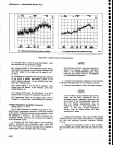
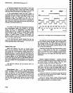
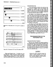
The
pattern
for
the
upper
address and
data
lines is
shown in Figure
6€9.
From
address
or
data
line
7
to
linE
0,
each line changes
at
twic€ the rate of the
previ-
ous lin€, resulting
In 128 cycles on
the
LSB
lines. ThE
initial
pulse
on
the
upper
four
data lines is
not
part
of
the
+2
pattgrn
and
is not
repeated
on
the
lower
four
data lines. lt is
possible
to discover open
or
shorted
lines
by
comparing
the
patterns
to those
in Figure
6€9,
checking
that they
+t.
Look
for lines
that
stay high
or
low, change
together
or
at
wrong
times
in
the
pattern,
or
go
to
indeterminate
logic levels
(1
V to 2 V).
TROUBLESHOOTING
ON THE
INSTRUMENT
BUS
lnstrument
Bus
Data Transfers
There are
two
commands and
queries provided
to
aid
troubleshooting of circuit
functions
controlled by the
instrument
bus.
These
circuits
get
data
from
the
micro-
computer or
respond
with data
for
the
microcomputer.
The
ADDR
command
and
ADDR
query
set and
retum
the instrument bus address for
the
DATA command.
The DATA command
and
DATA
query
set and return
data
on
the
instrument
bus.
Because
th€ DATA command
changes
the
status
of internal
hardware,
its
use
may
prevent
normal
spectrum
Analyzer opera-
tion.
Incorrect
,settings
of some hardware
could
cause
instrument damage.
Maintenance
-
494A/494Ap
Servtce
Vol.
1
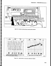
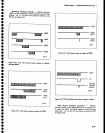
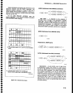
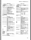
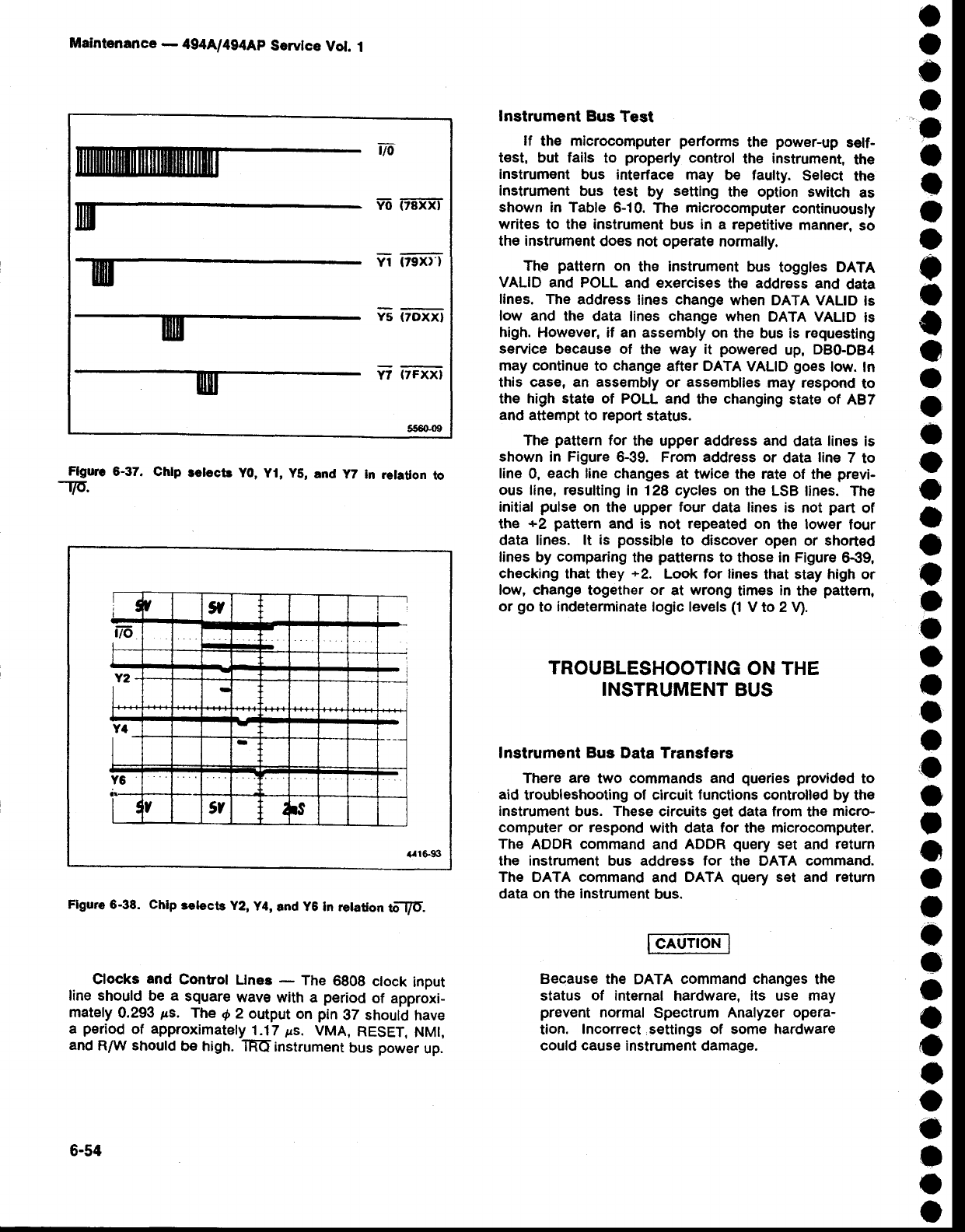
Chlp
relectr
Y0,
Yl, Y5,
and
y7
In
retadon
to
Flgure
G-38.
Chlp
relects
Y2,
y4,
and
y6
in relation
tilll6.
o
I
o
o
I
o
I
I
O
o
o
I
o
o
o
o
o
o
I
o
e
o
o
o
a
a
a
o
I
I
o
t
I
o
o
o
o
o
o
o
o
a
o
o
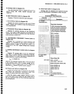
Flgurc
6-37.
-rlo.
Clocks
and
Control
Llnes
-
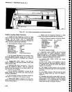
The
680g
clock
input
line should
be
a
square
wave
with a
period
of
approxi-
mately
0.293
ps.
The
c
2
output on
pin
37 shoutd
have
a
period
of
approximately
1.17;rs.
VMA,
RESET,
NMt,
and
R/W should
be high.
TFd
instrument
bus
power
up.
uo
It|l
woEm
Yr
iffiI
Y5
(70XXl
Y7
offii
556UX)
[[I
t[I[
6-54