


EXT VIDEO
SELECT
MARKER/VIDEO
15
VIDEO
FILTER
OUT
6,
11
INTERNAL
VIDEO
OATA BIT 1
RC FILTER
u20158
Theory
of Operation
-
4g4A/4g4Ap
Servtce,
Vol.
1
o
o
I
a
e
I
f
o
o
t
t
o
o
o
o
o
o
a
o
a
t
o
o
'l
o
o
a
o
o
o
o
o
a
o
I
o
o
J
I
O
o
o
I
t
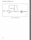
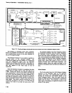
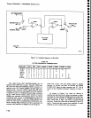
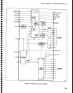
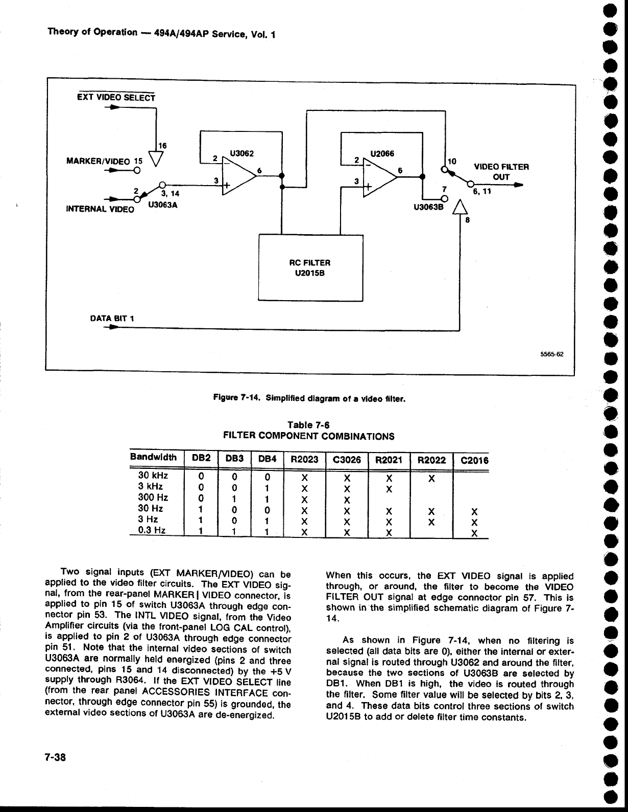
Flgure
7-14.
Simplllied
diagram
of
a video filter.
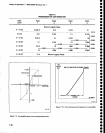
Tabte
7-6
FILTER
COMPONENT
COMBINATIONS
Two
signal
inputs
(EXT
MARKER/V|DEO)
can
be
applied
to the video
filter
circuits.
ThE
EXT
ViOeO
sig-
nal, from
the
rear-panel
MARKER
I
VIDEO
connector.
is
applied
to
pin
15
of
switch
U306gA
through
edge
con_
nector
pin
53. The
INTL
VTDEO
signal,
from
the
Video
Amplifier
circuits
(via
the
front-panel
LOG
CAL
control),
is applied
to
pin
2 of
U3063A
through
edge
connector
pin
51. Note
that
the internal
video
sectidns
of
switch
U30634
are
normally
held
energized (pins
2
and
three
connected,
pins
15
and
14
disconnected)
by
the +5V
suppry
through
R3064.
tf
the
EXT vtDEo
sELECT
tine
(from
the
rear
panel
ACCESSORIES
TNTERFACE
con-
nector,
through edge
connector
pin
55)
is
grounded,
the
external
video sections
of
UO063A
are
de-energized.
7-38
Wh€n
this occurs,
the EXT
VIDEO signal
is
applied
through, or around,
the filter
to becorne
th€
VIDEO
FILTER
OUT
signal
at edge
connector
pin
57.
This
is
shown in
the
simplified
schematic
diagram of
Figure
7-
14.
As shown in
Figure
7-14,
when
no tiltering is
selected
(all
data
bits are
0),
either
the internal
or
exter-
nal signal
is routed through
U3062 and
around
the
filter,
because
the
two
sections
of
U30638
are
selected by
DBl.
When
DB1
is high,
the
video
is
routed through
the filter.
Some
filter
value
will
be
setected
by
bits 2, 3,
and
4.
These
data bits control
three
sections
of
switch
U20158
to
add
or
delete
filter
time constants.
Bandwldth
DB2
DB3
DB4
R2023
c3026
R2021 R2022
c2016
30
kHz
3
kHz
300
Hz
30 Hz
3Hz
0.3 Hz
0
0
0
1
I
1
0
0
1
0
0
1
0
't
1
0
1
1
X
X
X
X
X
X
X
x
X
X
X
X
X
X
x
x
X
X
X
x
X
X