


Mafntenance
-
4g4ful4g4Ap
Servtce
Vot.
1
1ST
LO
CONTROL
DIAGNOSTIC
AID
NOMINAL
-6.79
V
3.43
V
DESIRED
2.720
504
c|-1.z
45.896
MHZ
DAC
TUNE
VOLTS
SENSE
VOLTS
lST
LO FREQ
MIXER
FREO
1ST
LO
SETNNG
ACCURACY
AUXILIARY
SYNTHESIZER
PRESS
'SH|FT"
TO
EXIT
-6.80
V
3.43 V
2.719
735
cHZ
46.665
MHZ
4.981
MHZ
212.800
MHZ
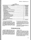
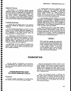
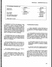
The
Desired
l
st
LO
Freq
is
th€
frequ€ncy
to
which
llre
qroge.ssor
,is
trying
to
move
the
oscillator.
The
uounted
l
st
Lo
Freq
is
the frequency
the
microcom-
puter
has
calculated
from,
the
internalty
counted
har-
monic
mixer
output
frequency,
the
Auxiliiry
Synthesizer
frequ€ncy,
and
the assumed
harmonic
numOer
of
the
Auxiliary
Synthesizer.
BEcause
of
this
lasi
assumption,
if
the
lst
LO
is
not
near
the
Desired
Frequency,
the
counted
Frequency
wiil
not
be
the
actuar
osciilator
fre-
quency,
even
though
the
counter
is
functioning.
The
Desired
Mixer
Freq
is
the
difierence
between
the the Desired
1st
LO
Fr€q
and
the
nearest
harmonic
of
the Auxiti.ary
Synthesizer.
(fhe
Auxitiary
Synthesizer
laryolig
wiil
atways
be higher
in
frequency
than
rhe
desired
lst
LO
frequency.)
The
1st
LO
Setting
Accuracy
is
the
maximum
per_
mitted
difference.between
the
actual
and
desired
LO
frequencies.
The
setting
process
will
end
when
the
difference
becomes
less
than,
or
equal
to,
this
value.
The
tolerance
depends
on
frequency
span
and
band.
.. -T"
Auxiliary
Synthe.sizer
Freq
is
the
frequency
that
is
programrned
into
the
+N
synthesizer.
This
troubleshooting
procedure
should
localize
a
problem
to
the oscillator,
the oscillator
setting
block,
or
the.oscillator
counting
block.
lf
the failur€
is
not
in
the
oscillator,
it
is
further
localized
within
one
of
the
hardware
blocks.
Troubleshooting
procedure
1.
Press
<Btue-SHtFT>
PULSE
STRETCHER
and
#3
to
display
the Diagnostic
Aids
menu,
then
sefect
#1
to
display
the
1st
LO
Control
Diagnostic
Aid
informa-
tion.
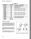
2.
lf
the counted
lst
Lo Freq
is
within
the
1st
Lo
Setting
-Acgyracy
of
ths Desired
Freq
readout,
press
<Blue-SHIFT>
to
retum
to
normal
operation.
Now
detennine
if
the
error
occurs,
for
the same
center
fre-
quency,
at
frequency
spans/division
above
S
MHz
only,
or
at
spans
less
than
5
MHz/div.
(Frequency
range
must
be
0
-
1.8
GHz
or
i.fl(em
5.5
GHz.)
a.
lf
the
frequency
control
error occurs
only
at fre_
quency
spans
of
5
MHz/div
or
more,
the capacitor
switching
relay,
on
the 1st
LO
assembly,
is
probably
shorted.
(E)
b.
lf
the error occurs
with
a
frequency
span/div
of
5
MHz or
less,
the
1st
LO is
probably
defective. (E)
3,
Measure
the
voltage
across
th€
sense
resistor
(R1040)
on
the
lst
LO Driver
board. tf
this
vottage is
within
50 mV of
the
DAC
Set
value,
measure
the
fre-
quency
on
the
l
ST LO
Output
connector.
This meas-
ured frequency
should
be within
S0 MHz
of
the
fre-
quency
calculated
by multiptying
800 MHz/V
by the
vot-
tage
that
was measured
across
the sense
resistor
R1040.
6-9