


Theory of
Operation
-
4g4A/4g4Ap
Service,
Vol.
l
puter
tunes
the
l st
LO
frequency
through
the following
sequence;
up 750 kHz,
down
i.5
MHz,
up
1.5 MHz,
ani
down
750
kHz.
During
one
of
these
yirmware
searches,'
the lst
LO frequency
passes
through
the strobe
har-
monic frequency
and
th€
loop
acquires
lock.
Any
frequency
difference
between
the
strobs
signal
and
the 1st
LO
will
generate
a low
frequency
conection
voltage.
This
correction
voltage
is
filtered
by
the
F(s)
amplifier,
then
used
to
drive
the oscillator
FM
ioilto puti
the oscillator
frequency
back
to
the strobe position.
tf
th€ lst
LO
drifts
beyond
the error
voltage
range
of
the
F(s) amplifier,
comparators
on
the Error
Amplifier
board,
that monitor
the
error
voltage,
wilt
interrupt
the
micro-
computer
and
indicate
the
direction
of
drlft.
The
micro-
computer
then
tunes
th€
center
Frequency
control cir-
cuits
to null out
any
FM
coil
current
in
thL
phase
tock
loop.
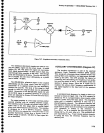
Frequency
Control
The
21
-bit
counter
and
its
associated
control
circui-
try,
on
the Counter
board,
plus
the
Harmonic
Mixer
and
Auxiliary
Synthesizer,
form
the
frequency
control
hardware
nucleus
for
the
spectrum
analyzer.
A
firmware-based
control
loop,
that uses
data
from
the
counter
as
feedback
on
the oscillator
frequency,
con-
trols both
the lst
LO and
the
2nd
LO frequenciel.
tne
l0MHz
lF is
also
counted
by
the
Counter
to
d€termine
the input
signal
frequency
to th€
analyzer.
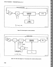
A mix
down
counting
scheme
is
used
to
count
the
lst
LO frequ€ncy,
which
varies
between
2 GHz
and
6 GHz.
'fhe
2O0-220
MHz
output
from
the
Auxiliary
Synthesizer
is
positioned
so
one of
the
signal harmon-
ics
is
approximately
45
MHz above
the lst
LO
fre_
quency.
This
output
drives
the
LO
input
to the Har-
monic
Mixer,
the
1st
LO
drives
the
RF
input.
One
of
the
lF outputs
from
th€ Harmonic
Mixer
is
within
the
10
to
80
MHz
range (approximatety
45
MHz).
This
tF signal
is
passed
through
a 10-80
MHz
band-pass
filt€r,
divided
by 100,
then counted
by the
Counter.
Since
the
proces-
sor
knows
the
Synthesizer
frequency,
the l st LO
fre-
quency
can
be calculated
if
the
processor
knows
which
harmonic
of
the
Synthesizer
frequency
was used
to
generate
th€
lF
frequency
being
counted.
The harmonic
of
the Synthesizer
frequency
is calculated
from
the 1st
LO
tuning
DAC
(digital-to-analog
converter)
code, since
it
indicates
the
1st
LO
frequency
to within
approxi-
mately *10
MHz.
Counting
the znd
LO
frequency
is
much
simpler.
The controllable
16-20
MHz
VCO
in
the 2nd
LO
assem-
bly determines
the frequency
of
the
2nd
LO;
therefore,
the
2nd
LO frequency
is
calculated
by
direcily counting
the 16-20
MHz signat.
The
2nd
LO
frequenty
is
then
calculated
from
this frequency.
Confolling fte O3clllator
Frequency.
The
fre-
quency
control loop is
only
closed
between
swesps.
After
the
completion
of
each
sweep,
the
processor
switches
the span/div
to zero and
then
counts
the
lst
LO and
the
2nd Lo
frequencies.
tf
they
ar€
not at
the
frequency
required
to
generate
the displayed
cEnter
tre-
quency,
they
ar6
set
to
the correcl
frequency
by
repeat-
ing
the
process
(i.e.,
the
DACs
are changed
to tune
the
LO,
the LO
is counted,
€tc.).
In
the single swsep
mode,
the
oscillator
frequencies
ar€ corrected
after
each single-swe€p actuataon.
and
before
th€
sweep
starts.
In
the
manual sweep
mode,
or
other
non-rscurring
sw€eps,
the
oscillators
ars
corrected
at
p€riodic
intervals.
Counting the lF. In
addition
to
counting
thE
fre-
quency
of
the
1st and
2nd
LO, the 10 MHz lF is
counted
when
the
Counter
mode
is
actuated;
thus, the
incoming
signal frequency can
be
calculated
from the frequency
conversion
equation for
the
analyzer.
The 1st
LO is
actually
phase
locked
before
the
2nd LO and
lF are
counted, in
order
to
reduce
FMing
in
the
lF signal.
This
allows
very
accurate
signal
counting, even
in
wide
spans.
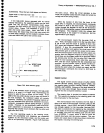
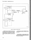
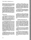
HARMONIC
MIXER
(Diagram
36)
The Harmonic Mixer combines
a
portion
of
the 2-
6 GHz 1st LO signal with harmonics of
the
200-
220 MHz refersnce
signal
from
the
Auxiliary
Synthesizer
to
provide
an
output
signal in the
10-80 MHz
range.
This signal is amplified
and
returned
to the
Auxiliary
Synthesizer where
it is counted
to
get
an
exact compu-
tation of
the
oscillator
frequency.
The Harmonic Mixer
consists
of
a
directional
coupler, an
input
amplifier,
the
mixer, and
an
output amplifier.
all
on
a hybrid circuit.
Figure
7-27 is a functional
block diagram
of
the
Har-
monic
Mixer.
Input signal level, from
the
lst
LO to dirgctional
coupler
A2541,
is a
about +10
dBm. The
coupling ratio
is 1O
dB, th€refore, the
coupler
will delaver
about l
mW
(0
dBm)
to
the
RF input of
the
harmonic
mixer. The
through-port
contributes about
0.5
dB
of
loss for
the
2-
6
GHz
signal.
The 200-220 MHz reference
signal,
at a
level of
about
10 mW
from
the Auxiliary
Synthesizer,
is
amplified
to
a level of about
100 mW
(+20dBm)
by
a
difier€ntial amplitier Ql
and
Q2.
Resistor R27 couples
the emitters together and
the
current
is
set by R13 and
Rl4.
Output
is
transformer coupled
to the
input of
the
mixer.
Input
signal level
to
the amplifier
is +7
dBm
minimum.
7-78