


Performance
Check
procedure
-
4g4A/4g4Ap
Service
Vol.
1
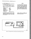
b. Activate
PULSE
STRETCHER
and
nore
that this
mode
extends
the talt
time
of
the
markers.
c.
Remove
the
test
equipment.
o
o
o
o
I
o
)
o
o
o
a
a
o
a
o
a
t
o
o
o
o
o
a
o
O
o
o
o
o
a
o
O
a
o
o
O
o
o
a
o
I
o
I
o
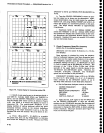
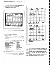
Figure
4€.
Typlcal
display
for
measuring
Time/Div
accuracy.
11.
Check
Resolution
Bandwidth
and
shape
Factor
(6
dB bandwidth
within
2ov"
of
the
s€lected
bandwidth;
shape
factor
is 7.S:l
or
less
lor
all
bandwidths
other
than
the 1O
Hz
bandwidth
which is
12:1
or less)
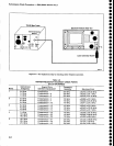
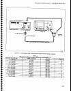
a.
Apply the
CAL
OUT
signat
to
the
RF lNpUT.
Set
the
Spectrum
Analyzer
controls
as
follows:
CENTER
FREQUENCY
sPAN/DrV
RESOLUTION
BANDWIDTH
REF LEVEL
VERTICAL
DISPLAY
MIN
NO]SE
PEAK/AVERAGE
TrME/DrV
TRIGGERING
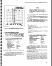
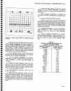
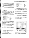
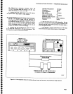
b, Measure
the
6 dB
down
bandwidth
(see
Figure
4-9A).
Bandwidth
shoutd
equal3
MHz
*600
kHz.
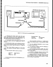
c.
Reset
the vERTtcAL
DtspLAy
to 10
dB/Dtv
and
measure
the 60
dB
down
bandwidth
(see
Figure
4_gB),
Figure 4-9.
Typical
display
for
measuring
bandwldth
and
shape factor.
d.
Check
that
the shape factor is
7.5:1
or less.
The
shape
factor is
the ratio
of
-60
dB/-6
dB bandwidths
{see
Figure
4-9).
e.
Reset
the RESOLUTION
BANDWIDTH
to
1
MHz,
SPAN/DIV
to 500
kHz, and VERTICAL
DISPLAY to
2 dB/DrV.
f. Check
the resolution
bandwidth
and shape factor
of
the
't
MHz
filter
by repeating
parts
b through d.
100
MHz
1 MHz
3 MHz
-20
dBm
2
dBlDtv
Activated
Fully
Clockwise
AUTO
FREE
RUN
ltl
-8dBDOWN
1
EANDW|OTH
/
\
r
I
t
I
\
E
-z!il
nl
€
.a
{a
t
{
{
.,aa
{
{
t-l.t DaT
gE
A"
t
rt||rhg
tG
doun
b.nffdtt|.
-0d8DowN
)?illt;l-
BAIIDWIDTH
I tl
I
t\ | |
S}IAPE
FACTOR
*ffi-"t
lt\r I
I
I+l
t+l
*r--zffrr*
t*l
V
E
-znl
.E
tt.atc
D
r
TI
.it
{
<
-
-
-l
{
-
-t-
Fr.t
Dfi
&E
a.
llolrtqlnq
COdA
dorn
DenrMrt0r
end
computhg
d'|Pc
tactot
556{r..6
4-14