


Malntenance
-
4S4Al4g4Ap
Servtce
Vol.
1
o
a
o
o
a
a
I
o
o
t
o
t
a
o
o
o
t
o
t
o
o
o
o
a
o
a
t
o
o
o
a
a
a
o
o
o
o
I
t
o
o
I
o
a
TRACE
MODES
Trace
Mode
provides
information
on
how
the fre-
quency
control
system
is
working.
lt
is
acc€ssed
by
pressing
<Blue-SHtFT>
PULSE
STRETCHER.
menu
item
#7,
then selecting
lst
LO
(menu
item
#1),2nd
LO
(menu
item
#2} MARKER
(menu
item
#3),
or
CORREG_
TION
TIMER
(menu
item
#4),
gRD
tF
dOUrur
(menu
item
#5),
or DISPLAY
RESULTS
(menu
item
#6).
Trace
Mode
1,
starts
tracing
the l
st
LO
control
actions.
Trace
Mode
2,
starts
tracing
the 2nd
LO
con_
trol
actions.
Trace
Mode
g,
starts
tracing
signal
counts.
Trace
Mode
4 starts
tracing
marker
conection
cycles.
Information
from
these
four
trace
modes
is
stored
in
RAM
and can
be disptayed
by
setecting
DtSpLAy
RESULTS
(menu
item
6) from
the
TRACE
MbDE
menu.
This mode
disptays
up
to 16
lines
of
data
gathered
by
the
trace
modes.
Information
used
is obtained
only
wh€n
the
internal
frequency
correction
occurs.
Thihs
correction
is
related
to
the
drift rate
of
the spectrum
analyzer.
The
time
between corrections
can
be as
long
as
30
s.
To assure
information
is
available,
change
th€ FREO
SpAN/Dtv
one
position
then
retum.
This
forces
the correction
cycle
to
occur.
For modes
1 and
2,
the flrst field
of
the
display indi-
cates which
mode
was
active
at
the
time
the informa-
tion was
gathered.
The
second
field
of
th€
display
indi-
cates
which attempt
at
tuning
or
correcting
the oscilla_
tor
the
data is for.
The
next
lield
contains
the
tuning
DAG settings
before
a
tune or conection
took
ptace.
The first
three
digits
are
the
upper DAG
settings,
the
next
three dagits
the
lowEr
DAC
s€ttings.
The
next
field
contains
the DAc
settings
after
the
tuning
or
correction
was
attempt€d.
Again,
the
first
three
digits are
the
upper DAC,
and
the
next
three digits
the
lower DAC
settings.
The next
field
indicates
the
time
delay
between setting
the
DACS
to
the new
values
and read-
ing
the resulting
frequency,
in
units
of
millisecond.
The
final
field contains
the frequency
of
th€ oscillator
in
question,
after
the tune or
correction
attempt.
Actually,
the displayed frequency
is
the beat
note
frequency
from
the auxiliary
mixer
for
the l st
LO
(in
KHz), and
the
16-20
MHz oscillator
frequency
for
the
2nd
LO.
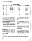
For
mode
3, the resulting
trace
display
consists
of
seven columns.
The
first
column
is
always
g.
indicating
that
the marker
is
being
traced.
The
second
column
gives
the iteration
number
of
the
correction
cycle
which
the displayed line
describes.
The
third column
consists
of two
lefters
and
a
number.
The first
letter is
p
if
the
6-14
data applies
to the
primary
marker
and
S
if
the
data
applies
to the secondary
marker.
The
second
letter
is
c if
th€
oscillators
are
being counted
at
the
marker
position
to determine
the marker
frequency,
or
S if
the
marker
position
is
being synthesized
to
maintain
a con-
stant
marker
frequency.
The
number
in
this
column
is
1
if
the 1st LO
is
being counted at
the
marker
and
2 if
the
second
LO is
being counted.
The fourth column
is the
hexadecimal setting
of
the marker
DAC. The
fifth
column
is
the
decimal digital storage
location
of
the
mark€r.
The
sixth column
is
the
oscillator
settling
time
in
ms
before
the
count.
The
last column
is
the
har-
monic
mixer output
frequency
in KHz for
a 1st
LO
count,
or
the
16-20
MHz
VCO fr€quency
for
a
2nd
LO
count
at
the
rnarker
position.
The
sequencE <Blue-SHIFT>
PULSE
STRETCHER,
#7, #0,
terminates
trace
actions
and erases
the RAM
of alldata.
Alternate
Frequency Display
The Alternate
Frequency
Display mode
selects
an
alternate
frequency display instEad
of
the
normal
Genter
Frequency
display. These alternate
frequencies
are
selected
by
pressing
<Blue-SHtFT>
PULSE
STRETCHER, selecling
menu item
#0, and selecting
#0, #1, or
#2 as indicat€d
by the
menu.
The normal
Center
Frequency
is displayed when
#0
is
selected.
The
frequency
of
the
1st
LO is
displayed
when
#1 is
selected.
This display is
updat€d
each
time ths
1st
LO
frequency
is counted.
The frequency of
the
2nd
LO is
displayed
when
#2
is
selected.
This display
is
updated each
time the tre-
quency
of
the
2nd
Lo is counted.
Auxiliary
Synthesizer Control
The Auxiliary
Synthesizer Control can be turned
on
continuously, or
turned
on only
during
correction
for
the
1st LO
tunes.
This mode is
toggled
(turned
on
continu-
ously or
during 1st LO
corrections)
by
pressing
<Blue-
SHIFT>
PULSE
STRETCHER,
and selecting menu item
#4, A message will
come
on screen indicating which
mode
the
Auxiliary
Synthesizer
is
in.
Correction Disable/Enable
Correction
of
the 1st
and 2nd LO frequencies can
be
disabled
or enabled
by
pressing
<Blue-SHIFT>
10
dB/DlV or
<Blue-SHIFT> PULSE
STRETCHER,
and
selecting
menu item #6. When
corrections
are
dis-
abled.
the
oscillator frequencies
are counted but
no
further
action is taken. This mode
can
be used
to
moni-
tor the drift
of
the
oscillators
by
activating
the
respec-
tive trace
mode. When corrections are
disabled.
the
1st
LO
cannot
be
phase
locked!