


o
a
o
a
O
o
o
I
a
o
t
I
o
o
o
o
a
o
O
a
o
o
O
o
a
o
o
o
o
o
t
a
I
a
O
a
o
o
o
I
o
o
o
o
divide
and
offset
lhe
output
of
U1031
so
the
tune
vol-
tage
ranges
between
0 and
-12.5
V.
The
output
of
divid-er
Rl0gg/R1Og4
is
apptied
to
the
varactor
of
the
2192
MHz
microstrip
oscillaior
(2nd
LO).
This
closes
the
phase-lock
toop,
tuning
if,"
ZnO
LO
so
!l"l-j! 9t9JrV
tracks
the
IB'MHZ
vto.
when
the
18
MHz
VCO
is
tuned,
Ul0gt
simuttaneousty
tun€s
the
microstrip
oscillator
an
equal
amount.
Within
the toop
bandwidth,
the
2nd
LO performance
is
OeiermineO
Uy
the
18
MHz
VCO
instead
of
the
microstrip
osciilator,
giving
a significant
imprwement
in
frequency
stabitity
and
reduction
of
phase
noise.
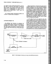
829
MHz
2nd
CONVERTER
(Diagrams
15
and
16)
The
829
MHz
2nd
ConvErter
assembty
(A23)
down-
converts
the
lst
Converter
band
2-4
g2g
irtHz
lF
signal
to 110
MHz
to
drive
the
3rd
Gonverter.
lt
also
provides
the switching
to select
either
the
2Ot2
MAz
2nd
Con-
verter
or
the
829
MHz
2nd
Converter.
The
lF
circuits
in
the
signal
path
are
shown
on
diagram
16,
tF
Section.
The
local
oscillator
circuits
are
sh-own
on
diagram
15,
LO
Section.
lF
Section
(Diagram
16)
The
829
MHz
lF circuits
include
an
input
diplexer,
an
amplifier,
a
band-pass
filter,
a
mixer,
and
a
diode
switch.
Theory
of
Operation
-
4g4[l4g4Ap
Servtce,
Vot.
1
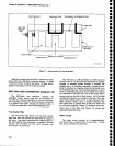
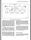
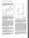
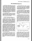
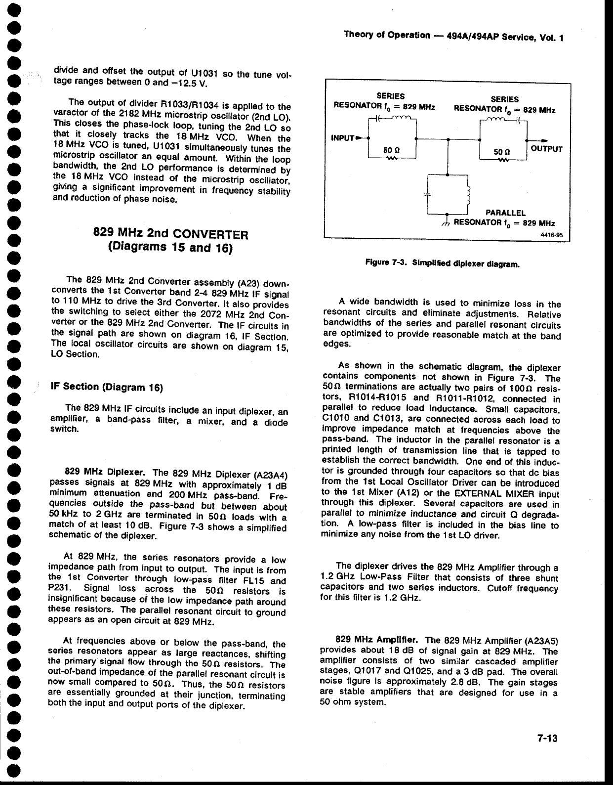
Flgure
7-3.
Stmpllfied
dlplexer
diagram.
A
wide
bandwidth
is
used
to minimiz€
loss
in
the
resonant
circuits
and
eliminate
adjustments.
Relative
bandwidths
of
the series
and
parailel
resonant
circuits
are
optimized
to
provide
reasonable
match
at
the
band
edgEs.
As
shown
in
the
schematic
diagram,
the diplexer
contains
components
not
shown
in
Figure
7-3.
The
50o
terminations
are actually
two
pairs
bt
i00O
resis_
tors,
Rl014-R1015
and
Ri011-Ri0t2,
connect€d
in
parallel
to reduce
load
inductance.
Small capacitors,
C1010 and
C1013,
are connected
across
each
load
to
improve
impedance
match
at
frequencies
above
the
pass-band.
The
inductor
in
the
parallel
resonator
is
a
printed
l€ngth
of
transmission
line
that is
tapped
to
establish
the correct
bandwidth.
one
end
of
this induc-
tor
is
grounded
through
four
capacitors
so
that
dc
bias
from
the lst
Local
Oscillator
Driver
can
be
introduced
to
the
lst
Mixer
(A12)
or
the EXTERNAL
MIXER
input
through
this
diplexer.
Severat
capacitors
are
used
in
paraflel
to minimize
inductance
and
circuit
e degrada-
tion. A low-pass
filter
is
included
in
the
bias
line
to
minimize
any
noise
from
the
1st LO
driver.
The
diplexer
drives
the
829
MHz
Amptifier
through
a
1.2GHz
Low-Pass
Filter
that consists
of
three shunt
capacitors
and
two series
inductors.
Cutoff frequency
for
this filter is
1.2 GHz.
829 MHz Amplitier.
The
829
MHz
Amptifier
(A2SA5)
provides
about
18 dB
of
signal
gain
at
g2g
MHz.
The
amplifier
consists
of
two
similar
cascaded
amplifler
stages,
Q1017
and
Q1025,
and
a
3 dB
pad.
The overall
noise
figure is
approximately
2.8
dB. The
gain
stages
are stable
amplifiers
that
are
designed
for
use
in
a
50 ohm
system.
829
MHz
Diptexer_.-
The
829
MHz
Diptexer
(A23A4)
passes
signats
at
929
MHz
with
approximateiy
f
Ofi
rninimum
attenuation
and
200
MHz' pass-band.
Fre-
quencies
outside
the
pass-band
but
betvyeen
about
50 kHz
to 2
GHz
are
terminated
in
50O
loads
with
a
match
of
at
least
10
dB.
Figure
Z-3
shows
a
simplified
schematic
of
the
diplexer.
At
829
MHz,
the
series
resonators
provide
a
low
irnpedance path
from
input
to output.
fnl
input
is
from
the 1st
Converter
through
low_pass
filter
FL.l
5 and
P231.
Signal
loss
across
the
SOO
resistors
is
insignificant
because
of
the
low
impedance
path
around
these r€sistors.
The
paraltet
resonant
circu'lt
to
ground
appears
as
an
open
circuit
at
929
MHz.
At
frequencies
above
or
below
the
pass-band,
the
s.eries.
r€sonators
app€ar
as
large
reaciances,
shifting
the
primary
signal
flow
through
the
50O r€sistors.
The
out-of-band
impedance
of
the
parallel
resonant
circuit
is
now
small
compared
to
S0O.
Thus,
the
50O resistors
are.
essentially
grounded
at
their
junction,
terminating
both
the input
and
output
ports
of
the
diplexer.
SERIES
RESONATOR
fo
:
829
MHz
SERIES
RESONATOR
lo
=
829
MHz
500
OUTPUT
PARALLEL
RESONATOR
fo
:
829
MHz
44.t695
7-13