


o
o
a
o
o
I
o
o
o
a
I
o
o
t
o
I
o
o
o
a
o
o
o
o
o
o
o
o
I
o
o
o
a
o
o
o
O
o
o
o
a
o
o
o
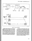
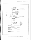
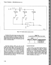
The
digital
control
circuits
receive
and
decode
the
address
and
instructions
from
the
microcomputer,
select
the
.
sweep
rate,
holdoff
time,
trigger
sourcer
sweep
mode,
control
marker
dac, and
cont?it
interrupts
to the
microcomputer.
.^.I"_I:rIT.
DAC
provides
a
dc levet
corresponding
ro
tne marker
sweep
position.
The
Sweep
board
analog
section
consists
of
the
?Ip 9r
sweep
generator
ptus
tts
output
buff€rs
that
drive
the
deflection
amplifiers,
the
osclllators,
digital
storag€,
Z
axis,
and
the
trigger
circuits.
The
sweep
and
trigger circuits
are
digitally
controlled.
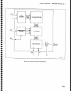
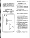
Digital
Control
-
Three
instrument
bus
addresses
are
associated
with
th€ sweep
board.
Addresses
0F
and
1F
are
write
addresses
and
9F is
a
read
address.
Two
bits
at
addr€ss
lF
subdivide
address
0F into
four
subad-
dresses.
Bus
decoder
U40gO
outputs
lows
for
addresses
0F,
1F,
and
9F.
U4020
bufiers
the instrument
bus
data
bits.
U1027
is
used
as
a
6-bit
register
to
hotd
data
at
address
lF.
Data
bits
6 and
7
go
to
U1030
which
decod€s
which
of
Ui03S,
U2O3O,
UiO+S,
and
Ul040
ar€
activated
at
addr€ss
0F
by
U4Og0.
ThesE
registers
store
the
microcomputers
latest
commands
lexc-pt
for
the
trigger
single
sweep
and
the abort
sweep
com_
mands,
which
are
not
stored)
and
they
control
most of
the op€ration
of
the sweep
board.
Commands
that
can
be
written
arE:
o
sweep
start
for
singte
sweep
mode
(bit
3 of lF
high).
o
Intemal
frequency
reference
on
or
off
(bit
4
of lF
tow
for
on
and
high
for
ofr).
o
Single
sweep
operation
(bit
0 of
0F.0
high).
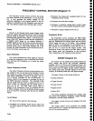
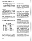
o
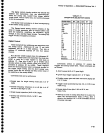
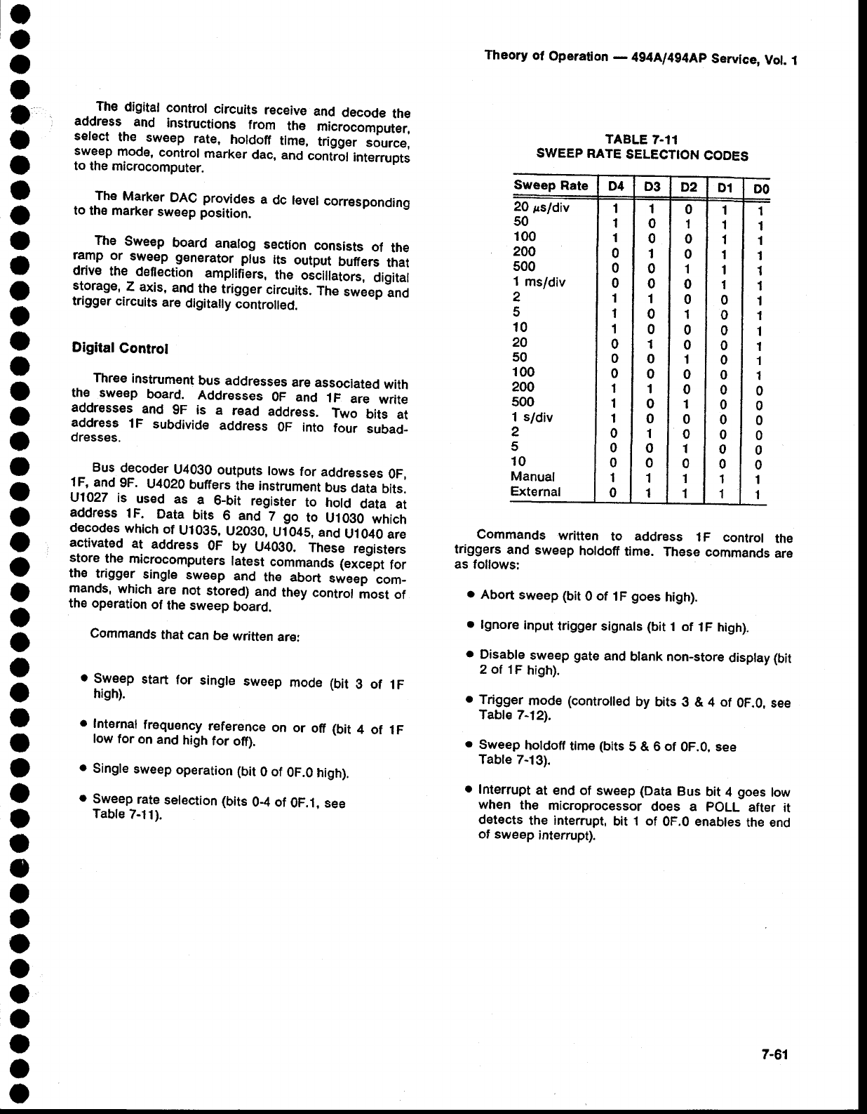
Sweep
rate
selection
(bits
0-4
of
0F.1. see
Table
7-11).
Theory
ol
Operation
-
4g4[l4g4Ap
Servtce,
Vol.
.t
TABLE
7.11
SWEEP
RATE
SELECTION
CODES
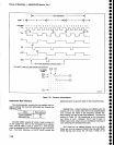
Commands
written
to
address
1F
control
the
triggers
and
sweep
holdoff
time.
These
commands
are
as
follows:
.
Abort
sweep (bit
0
of
tF
goes
high).
o
lgnore
input
trigger
signals (bit
1 of
1F high).
o
9islble
sweep
gate
and
btank non-store
disptay
(bit
2 of 1F
high).
o
Trigger
rnode
(controiled
by bits
g
&
4 of
0F.0,
see
Table
212).
.
Sweep
holdoff
tim€
(bits
5 & 6 of
0F.0, see
Table 7-13).
.
Interrupt
at end
of sweep
(Data
Bus
bit 4
goes
low
when
the
microprocessor
does a
pOLL
after it
detects
the
interrupt,
bit
1 of
0F.0 enables
the end
of sweep
interrupt).
Sweep
Rate
D4
D3
D2
D1
DO
20
ssldiv
50
100
200
500
1
ms/div
2
5
10
2A
50
100
200
500
1
s/div
2
5
10
Manual
External
1
1
1
0
0
0
1
1
1
0
0
0
1
1
1
0
0
0
1
0
1
0
0
1
0
0
1
0
0
1
0
0
1
0
0
1
0
0
1
1
0
1
0
0
1
0
0
1
0
0
1
0
0
1
0
0
1
0
1
1
1
1
1
1
1
1
0
0
0
0
0
0
0
0
0
0
0
0
1
1
1
1
1
1
1
1
1
1
1
I
1
1
0
0
0
0
0
0
1
'l
7-61