


Theory of
Operation
-
4g4[l4g4Ap
Servtce,
Vot.
1
Transistors
Q1017
and
Q1015
provide
curr€nt
for
the
trace rotation
coil.
Trace
Rotation
adjustment
Rl021 sets
the current
so
the
displayed
trace
is aligned
with
the
graticule.
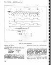
Power-Fail
Detector
This
circuit
detects
an
instrument
power
failure
and
transmits
th€
information
to the
processor
and
Memory
boards. The
LINE
TRIGGER
signat
from
the
powei
Supply board
through
edge
connector
pin
60 is supplied
to Q2011.
Q2011
buffers
the signat and
appties
lt
to
the
anput
of
retriggerabte
on€-shot
U20g4A.
U2034A
per-
forms
as a
missing-pulse
detector
to
generate
a
power-fail
signal
through
O30l
l to
notify
the
processor
and
Memory
boards
if
more
than
two 60 Hz cycles
are
dropp€d.
To avoid
an
undefined
state,
the output
from
U2034A is latched
tow
by
U2051.
Under normat
operat-
ing
conditions,
the POWER-FAIL
signal from
e3011
is
high.
Power-Supply
Monitor
This circuit
detects
if one
or
more of
the
instrument
power
supplies
have
failed.
Each voltage
supply
in
the
instrument
is
fed
into
thick film
resistor
network
RgOSl,
which
balances
th€ currents
to
provide
a
null output
(approximately
1
Vdc).
Any
line change
of
more
than
*,25oh
drives
the
input
to window comparator
U3OSI
beyond its
*200
mV
threshold
and
generates
a
low out-
put.
02059
and
Q2067
drive
the
duat
tight
emitting
diode
DS1062
to
provide
visual
indication
of
power-
supply status (grEen
indicates
normal operation
and
red
indicates a fault
condition).
The
output
of
U3051 is also
fed
to tri-state
buffer
U3052.
After
instrument
power
up
or
if a failure
is detected,
the microprocessor
will
poll
address
CF
to determine
power-supply
status
over
the
data bus.
Options
Switch
Switch
S1010 works
with
switch
S1050
on
the
Memory
board
(A54)
to configure
the
firmware
for
use in
various instruments
and
options.
Settings
are
noted
on
the schematic
diagram.
U3052
places
the switch
data
on
the
instrument
data
bus at
pow€r-up
as
described
above
for th€ Power-Supply
Monitor.
Timer
An
electromechanical
timer,
Ml019,
is calibrated
for
a
duration of
5000
op€rating
hours.
The
current
through R1015
and
the
timer causes
the
copper
band
to
progress
along
the scale.
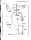
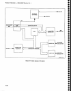
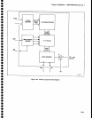
HTGH,VOLTAGE
SUPPLY
(D|AGRAM
29)
The High'Voltage
Supply furnlshes
the
-3860
V
crt
bias and
6.3
Vac filam€nt
voltage
to the
crt
cathode,
and
provides
dc
restoration
for
the Z-AXIS
DRIVE
sig-
nal.
Th€ supply
consists
of four main
circuits:
1. The high-voltage
oscillator
circuit
produces
the
crt filament
voltage and
the
2@
vac
that is stepped
up
and applied
to the
voltage
doubler circuit.
2. The voltage
doubler
circuit
rectifies
and filters
the
high voltage for application
to
the
crt
cathode.
3.
The high-voltage regulator circuit
samples
the
high
voltage and regulates
the
op€ration
of
the
high-voltage
oscillator.
4.
The Z-Axis
clipper and
rectifier circuits
couple
the
z-Axls
DRIVE
signal to
the
crt control
grid.
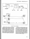
High-Voltage
Oscillator
This circuit consists of
transistor
01073,
transformer
T2065.
and
associated components.
The
approximately
200
Vac, oscillator
output is coupled
across T2065,
where it is
stepped
up
for application
to
the voltage
doubler,
and stepped
down
for application
to the
crt
filament.
Voltage Doubler
The voltage
doubler
consists of
CR4041, CR4035,
C4027,
C5021, C4024,
R3038, and R1039. The output
of
the doubler is taken
ofi
the
anode of
CR4035
and
applied
to the
crt
cathode
through the
filter consisting of
R3038,
R1039,
and
C4024.
Reference
voltage
for
the
regulator is
also
taken
off
the
end of R1039. R1039
keeps the filament
at
the
same
potential
as
the
cathode.
High-Voltage Regulator
This
circuit
consists
of amplifier
U4083
and sur-
rounding components.
The high voltage
is applied
through
a voltage
divider
that
consists of R1017B
and
R1017C. This voltage divider
is connected through
R1042
to
+15 V.
The sample
of
the
high voltage
at
pin
U
is
applied through
R4075
to the
input
of
comparator
U4083.
The correction
signal, in the
form of
dc
drive,
is
applied as
bias to
Ql073
to
set
the
oscillator current.
o
o
o
o
o
o
o
o
o
o
o
o
o
o
o
o
a
o
o
o
o
o
o
O
o
o
o
o
o
o
O
I
a
o
o
o
a
o
I
o
o
a
o
o
7-50