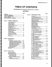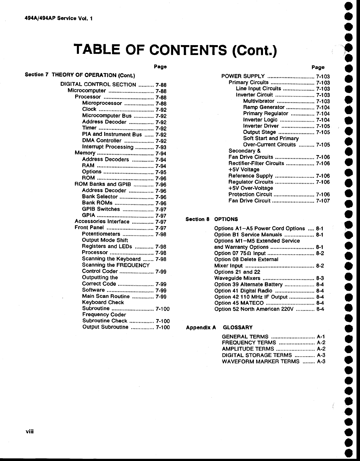
TABLE
OF
CONTENTS
(Cont.)
Page
Section
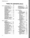
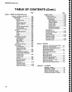
7 THEORY
OF
OPERATTON
(Conr)
DtctTAL
CONTROL
SECTTON
.......... 7_88
Microcomputer
.............................
7-gg
Processor
.............
7-gg
Microprocessor
...................
7-88
Cfock .........
......7-92
Microcomputer
Bus
........,....
T-92
Address
Decoder
................
Z-92
Timer .........
......7-gz
PIA and
lnstrument
Bus
...... 7-92
DMA
Controller
.............
......
7
-gz
Interrupt
Processing
...........:
7-93
Memory
.................2-94
Address
Decoders
..............
7-94
RAM
..........
......7-94
Options
.............
7-95
ROM ..........
......7-96
ROM
Banks
and
GptB
.............
7-96
Address
Decoder
................
7-96
Bank
Selector
......................
7-96
Bank
ROMs
.....
7-96
GPIB
Switches
...............,....
7-97
GPfA
..........
......7-97
Accessoriss
Interface
.......,.,....
Z-gT
Front
panel
..........
7_97
Pot€ntiometers
....................
7-98
output Mode
shift
R€gisters
and
LEDs
............ 7-98
Processor
...,.... 7-98
Scanning the Keyboard
....... 7-98
Scanning
the FREQUENCY
ControlCoder
.. 7-gg
Outputting
the
Correct
Code .......................
7-99
Software
.......... 7-gg
Main
Scan
Routine
..............
7-99
Keyboard
Check
Subroutine
.......7-100
Frequency
Coder
Subroutine
Check
................
7-1 00
Output
Subroutine
...............
7-100
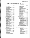
Page
POWER
SUPPLY
..........7-103
Primary
Circuits
........
7-103
Line
Input
Circuits ....................
7-1 03
Invert€r Circuit
..... 7-103
Multivibrator
....
7-103
Ramp
Generator ..................
7-l
04
Primary
Regulator
...............
7-1 04
Inverter
Logic ......................
7-1
04
Inverter
Driver
.............,.......
7-1 05
Output Stage .............,.........
7-1 05
Soft Start
and
Primary
Over-Current
Circuits ......"... 7-1 05
Secondary &
Fan Drive
Circuits ..... 7-106
Rectifi er-Filter Circuits ..................
7-1 06
*5V
Voltage
Reference
Supply
Regulator
Circuits ..... 7-106
+5V
Over-Voltage
Protection
Circuit ...... 7-106
Fan
Drive
Circuit
-......7-107
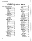
Sectlon
8
OPTIONS
Options
A1-A5 Power
Cord Options ....
8-1
Option Bl
Service
Manuals ...................
8-1
Options Ml-MS
Extended Service
and Wananty
Options ........
8-1
Option
07
75O Input
..............................
8-2
Option 08
Delet€
External
Mixer Input
....8-2
Options 21 and 22
Waveguide Mixers .............
8-g
Option 39
Alternate Battery ...................
84
Option
41
Digital Radio .........................
8-4
Option
42110 MHz
lF Output
................
8-4
Option
45 MATECO ...........
8-4
Option
52 North American
220V ............
8-4
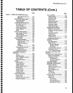
Appendlx A GLOSSARY
GENERAL
TERMS ........ A.1
FREQUENCY TERMS ...
A-2
AMPLITUDE TERMS
.....
A-2
DIGITAL
STORAGE
TERMS ..-.......... A-3
WAVEFORM
MARKER
TERMS
........ A-3
o
a
o
I
,
a
o
o
a
o
a
I
o
t
o
t
a
o
o
I
a
a
o
o
o
o
a
o
t
a
o
I
o
o
o
I
o
o
I
o
O
o
o
o
4944/494AP
Servlce
Vot. 1
v||l


