


Malntenance
-
4g4A/4g4Ap
Servlce
Vol.
i
1st
Converter
Bias
This
procedure
presets
flatness
for
Band
4, Band
5,
and Bands
'1,
2,
and
3,: then
adjusts
the
Start
(O
Hzi
Response
amplitude
and
overall
flatness.
These
adjustments
should
only
be
performed
after
replacem€nt
of
the
Dual
Diode
Assem'bly
in
the
First
Converter.
Test
equipment
needed
to adjust
the
1st
Converter
are
listed
in
Table
6-9.
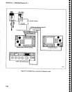
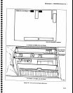
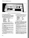
a.
Remove
the
lst
Converter
assembly
from
the
Speetrum
Analyzer.
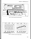
Connect
the assembly
t6
the Spec-
trum Analyzer
as
shown
in
Figure
G26.
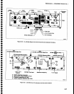
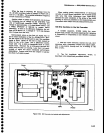
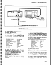
b. Monitor
Tp1011
on
the
lst
LO
Driver
board
with
a_voltmeter (meter
ground
at
crt
shield).
See Figure
6_
27
tor
the
location
of
Tpl01
1.
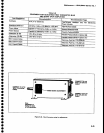
c.
Set
the
Spectrum
Analyzer
controls
as
follows:
i.
Set the
SG503 output
frequency
at
2 MHz,
and
output level
at
0 dBm
as indicated
on
the
power
Meter.
j.
Disconnect
th€ 50O cable
from
the
power
Meter
and
connect
the cable
to the
Spectrum
Analyzer
RF
INPUT
through
the 10dB
and
gdB
attenuators.
The
CENTER may
have
to be
reset
to
bring
the
2 MHz
sig-
nal
to
center
screen.
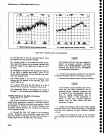
k Activate
SAVE A
to
save
the bandwidth
of the
2 MHz for
reference.
l. Monitor
TP1011
on
the
lst LO
Driver
board
with
the
voltmeter.
m.
Preset R1013
on
the
1st
LO
DrivEr
board for
-1.0
V at
TP1011.
n. Reset
FREQUENCY
to
0
(0.00
MHz)
to bring
the
0 Hz
spur
to
center
screen.
t
a
o
t
o
O
o
o
o
o
o
I
o
a
t
I
o
o
o
t
t
o
o
a
t
I
a
a
a
t
I
a
o
o
t
o
o
a
o
o
o
I
o
a
TIME/DtV
REFERENCE
LEVEL
FREQUENCY
RANGE
FREO
SPAN/D|V
VIEW
A and
VIEW
B
MIN
RF
ATTEN
PEAK/AVERAGE
AUTO
-30
dBM
5.4-18
GHz
(Band
4)
MAX
ofi
0dB
Fully
Glockwise
DO NOT
ALLOW
THE
VOLTAGE
AT
TPlOll
TO
EXCEED
+0.1
V WHILE
THE
FOLLOWING
ADJUSTMENTS
ARE
BEING
MADE.
o. Adjust
the
tuning screw on
the 1st Mixer
assem-
bfy
and
R1013,
R1022,
and
Rl026 on
the
1st
LO
Driver
board
to
match
the
response
of
the
0
Hz
spur
to the
bandwidth of
the
2 MHz
reterence
(SAVE
A
disptay).
Auxiliary
Synthesizer
VCO
Adjustment
a.
Monitor
TP1066
on the Auxitiary
Synthesizer
board
with a voltmeter.
b.
Disconnect
P261, P1039, and
p1060
from the
Auxiliary
Synthesizer
module.
c. Disable
frequency
corrections
by
pressing
<Blue-SHIFT>
1
0 dB/DlV.
d.
Enable
the Auxiliary Synthesizer
by
pressing
<Blue-SHIFT>
pulse
STRETCHER
and
selecting
menu
item
#4.
e.
Adjust
Cl070 on
the
Auxiliary Synthesizer board
for +5 V at TPl066.
d. Preset
Bias
2
R1022
(Figure
6-271
tor
a
meter
reading of
-0.25
V.
e.
Change
the
FREQUENCY
RANGE
to Band
s
(15-21
GHz.)
f. Preset
Blas
3
R1026
(Figure
6_27)
for
a
meter
reading
of
-0.25
V.
g.
Reset
the
Spectrum
Analyzer
controls
as follows:
FREQUENCY
2MHz
FREOUENCY
RANGE
0-1.9
GHz
(Band
t)
FREO
SPAN/D|V
200
kHz
VIEW
A
and
MEW
B
On
WIDE
VIDEO
FILTEH
on
Calibrate
the
power
meter
before
making
measurements.
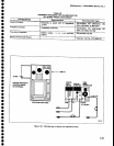
h.
Connect
a
50O
cable
from
the
output
of
the
SG503
to the Power
Meter
(Sensor.)
6-44