


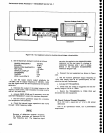

a.
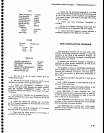
Connect
the
test
eguiprn€nt
as
shown
in
Figure
4-22.
Set
the
Spectrum
enityzer
"ontroi,
"i
fouows:
VERT|CAL
DTSPLAY
2
dB/DtV
T|ME/D|V
EXT
VIEW
A and
V|EW
B
Otr
b.
Set
the
function
generator
controls
for
no
output
(0
v).
c.
Use
thE
POSITION
"ontroi
to
position
the
crt
beam
-on
the left
graticule
edge.
This'est;btishes
the
0
V
reference.
d. Reset
the
function
generator
output
frequency
to
1
kHz,
and
increase
its
output
level
for
"
trti
t
O-Oiri"ion
sweep
on
the
Spectrum
Analyzer.
e.
Check
that
the function
generator
output
level
is
20
V
peak-to-peak
*2
V.
A variable
voltage
source
can
be
used
in
plac€
of
the
function
generator
to check
external
sweep
operation,
lf
used.
the
range
would
be
0V
to +10
V.
f,
Disconnect
and
remove
the
test
equipment.
Return
TIME/DIV
to AUTO.
Perfonnance
Check
procedure
-
4g4ful4g4Ap
Service
Vol.
l
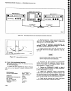
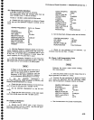
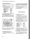
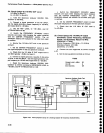
Pioa€
POWEF
\s7/^t
t15VMAX
CAUTION
Place
jumper
between pin
I
antl
pin
5
lo
selecl
EXTERNAL
VIDEO.
JIdACC-ESSORIT
pin
t,
Video
Setecr
-
NOT
RS232
COMPATIBLE
ooooooo?toooo
oooo
ococoooo
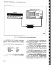
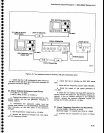
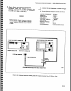
Figure
4-21.
Extemal
vldeo
select
plns
and
MARKER
IVIDEO
Input
Test
Oscltloscope
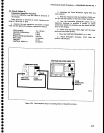
@
@
@
@".
ooooooo
Funclion
Generato.
Spectrum
Analyzer
Under Test
(Rear
Panel)
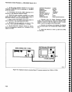
Figure
4'22'
Test
equipment
setup for
checking
external
triggering
and horizontal
input
characteristics.
4-33