


Theory
of
Operation
-
4g4Ll4g4Ap
Service,
Vot.
1
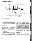
DETAILED
DESCRIPTION
The following
description
is arranged
by sections
or systems;
such
as lst
Converter, 2nd
Converter,
etc.,
followed
by circuit
analysis
of
the circuiis
within
that
section.
Each system
or section
is introduced
with
a
description
of
the system
using
the
section
block
diagram
found
in
ihe
oiagrams
section of
the Service
Manual,
Volume
2. This
is
followed
by
a
description
of Lach
cireuit
board or
miajor
circuit
within
the system.
The appropriate
block or
schematic
diagram
number
is included
in
the
text
h6adings
for
each section
or
part.
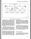
1ST
CONVERTER
SECTTON
(Diagram
2)
The 1st
Converter
consists
of
the
0-60
dB
step
Atenuator,
PreseleCtor,
lst
Mixer,
.lSt
LO,
power
Divider,
Transfer
Switch,
2.OT2
GHz Directional
Filter.
Diplexer,
and
two 4.5
GHz
Low-pass
Filters.
Externai
circuits
that
control
or
drive
the assemblies
within
the
l
st
Conv€rter
are:
the
preselector
Driver,
1st
LO
Driver,
Counter
and
phase
Loek
system,
and
the
RF
Interface
board.
The
1st
Converter
converts
the
incoming
RF
signals
to the lst
lF. lncoming
signals
are
applied
through
a
calibrated
0-60 dB
decade
attenuator
(AT10)
to
a
fitter
select
switch (S12).
Signats
in
band
t
(t
O
k|-tz
to
1.8GHz)
route
through
a
Limiter
(A10)
and
1.gGHz
Low-Pass
Filter (FLl0)
to
the
.tst
Mixer (A12).
Signats
in bands
2
through
S
(1.7
to
21
GHz)
route
through
a
tunable
Preselector
(FL12)
and
a
g
dB
Attenuator
(4T11)
to
the mixer.
The
RF signals
mix
with
the
output
from
a
tunable
localoscillator
(A16)
to
generate
products
at one
of
two
intermediate
frequencies,
depending
on
the band
in
use.
The
1st
Mixer output goes
to Directional
Filter
FL16
through
Transfer
Switch
S1B. The
transfer
switch
allows
input
from
the EXTERNAL
MTXER
input,
except
in
Option
07
and
08
instruments.
In
Option
0Z anO
0g
instruments,
the
EXTERNAL
MTXER
capability
is
deleted.
The
EXTERNAL
MIXER
input
permits
an
external
lF
source
(external
mixer)
to
be
connected
to
the instru_
ment.
The
lF
signals
from
external
mixers
are
routed
through
the Transfer
switch
to the
Directional
Filter.
This feature
allows
much
higher input
frequencies
by
using
waveguide
mixers.
The
direetional
filter
separates
the
2OTZMHz
and
829
MHz
intermediate
frequencies
for
the 2072 MHz
2nd
Converter
(A18)
or
829 MHz
2nd
Gonverter
(A23).
The
2072 MHz
lF
is apptied
through
a
4.5
GHz Low_
Pass
Filter
(FLl1)
to
the
2072
MHz 2nd
Converter.
The
829
MHz lF
is
fed
through a
Diptexer (A14)
and
another
4.5GHz
Low-Pass
Fitter (FL1S)
before
it
is apptied
to
the 829 MHz
lF
stages.
7-4
The
spectrum
analyzer
uses two
intermediate
fre-
guencies
(2472
MHz and
829 MHz)
to
prevent
basetine
rise caused
by
local
oscillator f€edthrough
and
cross-
over
of intermodulation
products.
The
2072
MHz
lF
is
selected
for
band I and for
bands
5
and above.
The
829 MHz lF is select€d
for
bands
2-4.
RF Interface
Circuits
(Diagram
28)
The
RF interface
circuits receive
instruction
from
the
microcomputer
and
produce
control
signals for
the
RF
Attenuator,
the
Transfer
Switch,
and
the
lF
Select.
These
RF control circuits
are located on
the Z-Axis/RF
Int€rface
board
(A70)
and
their
operation
is
described
under
the
z-Axis
board
part
of
th€
Display
section.
lst
Converter
(Diagram
12)
RF Input
The
RF INPUT
50()
connector accepts
the
input
sig-
nals in
bands 1
through 5.
Higher frequencies
require
external
waveguide mixers
that use the
EXTERNAL
MIXER input,
along with the
LO
outputs.
Option 07
instruments
have
a75A
input
in
place
of
the
EXTERNAL
MIXER connector. Transfer
Switch S13
selects between
the 50O
and
75O inputs.
The RF input
signal
goes
through
a
0-60 dB
Step
Attenuator
(AT10)
consisting of relay-controlled
10d8,
20 dB,
and
30
dB sections. The relays are
actuated
by
control signals
from
the
RF Interface circuit.
Preselector
Circuits
Coaxial switches
31
1
and
512
are relays
that
select
either
the low-pass filter
(FLl0)
and Limiter (A10)
or the
Preselector
and
3 dB
attenuator
(AT11)
for
the
RF
sig-
nal
path.
The relay coils are
driven by
circuitry on the
Preselector Driver
board.
The low-pass
filter
path
is
used for
band 1,
and
the
Preselector
path
is used
for
bands 2
through
5.
a
o
o
o
o
o
o
o
o
o
o
o
o
o
o
o
o
o
o
o
o
o
o
o
o
o
o
o
o
o
o
o
o
o
O
o
o
o
o
o
o
o
o
o