


o
I
o
C
o
t
o
t
o
o
I
)
t
I
C
o
a
o
o
c
o
o
t
a
o
o
o
o
o
o
a
o
a
o
o
o
c
O
o
o
a
o
I
o
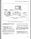
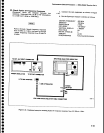
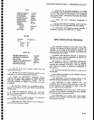
7L14
Center
Frequency
Freq
Span/Div
Hz
Resolution
Reference
Level
Display
Mode
Digitaf
Storage
TimelDiv
Triggering
Source
Mode
Video
Filter
110
MHz
1
MHz
3
MHZ
0
dBm
2
dBlDiv
off
Manuaf
Free
Run
Norm
On
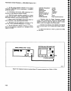
Performance
Check
procedure
-
4g4Al4g4Ap
Service
Vol.
1
j.
check
that
the
waveform
symmetry
is *1.0
MHz
(*1.O
division)
by
checking
that the
3 dBpoints
as
wetl
as
the
6
dB
points
on
the
waveform
are
equidistant
from
center
screen.
fl-he
peak
of
the
signal
miy
not
Oe
at
center
screen).
k.
Reset
the 7L14
Resolution
Bandwidth
to
0.3
MHz,
l.
Set the
ZL14
Center
Frequency
control
such
that
the intensified
dot is at
th€
p€ak
of
th;
7L14
disptsr.-'--
m.
Check
that
the
frequency
counter
indicates
a
frequeancy
between
1 t
g.5
MHz
anO
t t
t.S
MHz.
GPIB VERIFICATION
PROGRAM
This
verification
program
can
be
used
with
a
TEK-
TRONIX
4050-Series
Computer
TErminal
to check
the
operation
of
the
GplB in
the
Spectrum
Analyzer.
All
interface
lines
and
interface
messages,
excluding
those
for
parallel
poll,
are
verified.
In
addition,
the instrument
interface
is
checkEd
for
operation
on
other
primary
addresses,
as
well
as
the
talk-only
and
listen-only
modes.
The
program
is
written
in
TEKTRONTX
4OSO
BASIC,
and
is
divided
into individual
tests,
each
for a
sp€cific
interface
line,
message,
or
function.
The
tests
start
on
even
1000
line
numbers
to
allow
easy
modification
of
the
program.
The
following
describes
the function
of
each
test in
the
program.
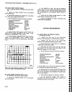
Lines
1-5000:
lnterfac€s
to user
definable
keys
for
recovery
from
a failed
test.
Lines
5000-6000:
Inputs
the
primary
address
of
the
Spectrum
Analyzer
under
test (1
shouldbe
used).
Lines
6000-7000:
tD query
response
test.
The
instrument
must
be
able
to
talk and listen,
to
send
out
its
lD?
response
and
manipulate
all
eight
of
the DIO
lines
for
the
test
to
be
successful,
Llnes
7000-8000:
Local
lock-out
test. Tests
correct
operation
of
the
interface
message
that
should
disable
all
programmable
front-panel
controls.
Lines
8000-9000:
Go
to
LOCAL
test.
Tests
correct
operation
of
the interface
message
that should
enable
all
front-panel
controls.
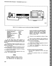
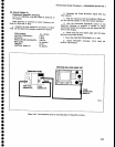
DC
509
Function
Frequency
A
chA
Source
Ext
Atten
X1
Coupl
Dc
Opton
42
CENTER
FREQUENCY
t10MHz
FREQUENCY
SPAN/D|V
1
MHz
REF
LEVEL
_30
dBm
RESOLUTTON
BANDW|DTH
1
MHz
VERTICAL
DISPLAY
2 dB/DIV
MIN
RF
ATTEN
dB
O
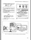
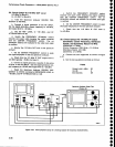
c.
set
the
7L14
dot
to
center
screen
with
the
Manual
Scan
control.
d,
Set
the 7L14
Center
Frequency
controt
for
an
indication
of
1j
0.0 on
the f
requeniy
Co'unter.
e.
swirch
the
FREQUENcy
spAN/DlV
control
tgward-s
zero
span
while
keeping
the
signaf
centered
with
the
oENTER
FREOUENCY
contr'ot.
The
crt
SPANiDIV
readout
will
indicate
10
ms
*t"n
."ro
"p"n
is reached.
f.
set
the
7L14
Time/Div
for
a
catibrated
disptay,
and set
the
Reference
Level
and
TR502
Var
dB
for
full
screen
signal.
g.
Switch
the
TRS02
Dot
Intensity
,,on",
and
reset
the
7L'l4
Center
Frequency
for
an
indiiation
o,
1
10.0
on
the Frequency
Counter.
h.
Check
that
the
3dB
bandwidth
(1.5
divisions
from
the
peak
of
the
signal)
is
)5
MHz.
_^i: th-"-"!_that
any
ripple
present
on
the
display
is
<0.5
dB
(0.25
divisions
or
tess).
4-39