


I
t
a
o
o
a
a
t
o
o
o
t
I
o
o
o
a
o
o
I
o
o
o
o
o
o
o
o
o
t
a
o
I
o
a
I
t
I
t
o
I
o
a
o
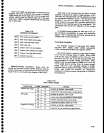
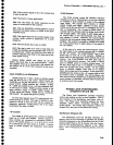
Theory
of
OperaUon
-
494Al4g4Ap
Servtce,
Vot.
1
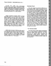
Output
Amplifier
LO
AIIPLIFIER
4416-200
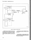
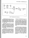
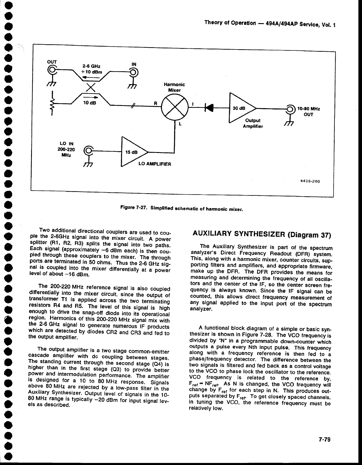
Flgute
7-27.
Slmplified
schematic
of harmoolc
mixer.
Two
additional
directional
couplers
are
used
to cou-
?f..lh" 1-9c!.
signat
into
the
mixer
circuit.
A
power
ll,ll"l,lll .12,
Rsl
sptits
the
sisnar
into
two
paths.
FFcn
stgnat
(approximately
_6
dBm
each)
is
then
cou_
pled
through
these
coupleis
to
ttre
mixer.
Tfre
ttrroujtr
ports
are
terminated
in
50 ohms.
Thus
the
2-6
GHz
iig-
nal
is
coupted
into
the
mixer
Oinerentiatty
at
a
power
level
of
about
-16
dBm.
The
200-220
MHz
reference
signal
is
also
coupled
differentially
into
the
mixer
circuit,
since
the
output
ot
::11^.j:jlT,
r1_
is:pptied
across
*,"
uJ
terminatins
restsrors
R4
and
R5.
The
level
of
this
signal
is
higi
enough
to
drive
the snap_off
diode
into
its-
operational
region.
Harmonics
of
this
2@-Z2O
Mnz
silna
mix
with
th.e.
?-6
GHz
signal
to
generate
numerouJ
lF
products
:vhich.ar:
detected
by
diodes
CR2
and
CR3
ano
fed
to
rne
output
amplifier.
The
output
amplifier
is
a
two
stage
common-emitter
cascade
amplifier
with
dc
couplinj
between
stages.
The
standing
curr€nt
through
ttre
sjconO
stage
(e4)
is
higher
than
in
the
first
stlge
(a3)
to
provide
better
power
and
intermodulation
performance.
Th€
amplifier
is
designed
for
a
10
to
gO
nl|Hz
response.
Signals
above
80Jr4Hz
are
rejected
by
a
tow-pass
filter
in
the
Auxillary
synthesizer.
Output
level
of
signals
in
the
10_
99 Yt-rltg.e
is
typicalty
-20
dBm
ror
inpri
sisnat
tev-
els as
described.
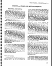
AUXILIARY
SYNTHES|ZER
(Diagram
37)
The
Auxiliary
Synthesizer
is
part
of
the spectrum
analyzeis
Direct
Frequency
Readout
(DFR)
systern.
This,
along
with
a
harmonic
mixer,
counter
circuiti,
sup-
porting
filters
and
amplifiers,
and
appropriate
firmware,
make
up
the DFR.
The
DFR
provides
th€ ,neans
tor
measuring
and
determining
the frequency
of
all
oscilta-
tors
and
the center
of
the lF,
so
the
cenier
screen
fre-
quency
is
always
known.
Since
the lF
signal
can
be
counted,
this
allows
direct
frequency
measurement
of
any
signal
applied
to
the input
port
of
thE spectrum
analyzer.
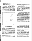
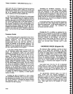
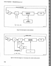
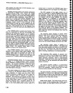
A functional
block
diagram
of a
simple
or
basic syn-
thesizer
is
shown
in Figure
7-2g.
The
VCO frequency
is
divided
by
"N"
in
a
programmable
down-counter
which
outputs
a-pulse
every
Nth
input putse.
This
frequency
along
with
a
frequency
reference
is
then
fed-
to
i
phase/frequency
detector.
The
difference
between
the
two
signals
is
filtered
and
fed
back
as
a control
voltage
to
the
VCO
to
phase
lock
the oscillator
to the r€ference.
VCO
frequency
is
related
to
the
reference
by,
Fret
-
NFrer_
As
N
is changed,
the VCO
trequency
will
change
by Frer
for
each
step
in
N.
This produces
out_
puts
separated
by Fr"r.
To
get
closely
spaced
channels,
in
tuning
the VCO,
the reference
frequency
must
be
relatively
low.
7-79