


o
o
o
o
o
o
o
o
o
o
o
o
o
o
o
o
o
o
o
o
o
o
a
o
o
o
o
o
o
o
o
o
o
o
o
o
o
o
o
o
o
o
o
o
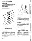
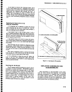
5.
Open
the
diode
package.
Use
a
pair
of
tweezers
to
grasp
th€
diode
assembly
by
its
side,
and place
it
on
a
static-free
surface.
Grasp
t-he
side
of
the'"rr"rOty
with^the
fingers.
Avoid
coniact
with
the
diodes.
Insert
the 8-32
screw.
6,
Orient
the
diode
assembly
so
the
three
contact
tips
are
arigned
with
their
respictive
contacts
in
the
mixer;
then,
using
the
index
fingers
of
both
hands
so
equal pressure
is
applieO,
presJ
the
subassembty
into
place.
7,
Insert
the
four
mounting
screws,
then
replace
and
tighten
the
three
coaxial
ionnectois
to
g
in-lbs.
Remount
the
lst
Conv€rter
assembly
Oy instatting
itre
two
mounting
screws
that
hold
ttre
aisembty
to
th;
RF
deck.
-. .
8. The
Spectrum
Analyzer
may
not
meet
the
flatness
specification
after
the Duat
CIode
assembly
is
replaced.
Refer
to
MATNTENANCE
ADJUSTMENTS
in
this_ seetion
for
a
procedure
for
adjusting
converter
bias
and
flatness.
Replacing
the
Crt
1.
Remove
the
snap_in
printed
bezel
and
crt
tight
filter.
.
2:
Use an
g/64
inch
AllEn
wrench
to
remove
the
four
bezel
screws,
unplug
and
remove
the inner
bezel.
3.
Unsolder
the
ground
wire
from
the
front panel
casting
and
unplug
the
crt
cables
at
their
respective
?oarg_
connections
(High
Voltage
module,
Deflection
Amplifier
board,
and
Z-Axis
UoarO;.
4.
Slide
the
crt,
with
its
shletd,
out
through
the
front
panel.
5. Remove
the
crt
shield
as
follows:
a.
Remove
the
tube
base
cap
and
unplug
the
socket.
b. Remove
the
two
side
screws
that
hold
th€
upper
shield
in
place,
then
remove
the shield.
c.
Loosen
the
screws
that clamp
the
plastic
bracket
around
the
crt,
then remove
the
bracket.
.
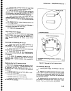
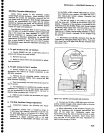
6.
Jnstall
the
plastic
bracket
so
the
back
on
the
ctamp
is
5.07
inches
from
the
back
of
the
cn
socket
guide.
-
7.
ReplacE
the crt
shield plus
the socket
and
base
shield
by reversing
the
removal procedure.
The
finished
crt
^assembly
length.
with
cap
installed,
must
equal
11.05
inches.
lf it
is
longer,
the assembly
may
short
cir_
cuit
the Deflection
Amplifier
circuit
boird
when
it
is
installed.
.
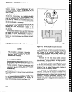
8..
Place
_
the
spectrum
analyzer
on
its
rear
panel
then
loosen
the
four
crt
blue
ptastic
mounting
blocks
on
the
front
casting
so
they
can
be
readily
positioned
when
the crt
is installed.
Maintenance
-
4g4Ll4g4Ap
Service
Vol.
1
9.
lnstall
the
crt
with
shield
assembly
through
the
front
panel;
seat
the wedges
on
the siOe
of
the crt,
into
the
blue
plastic
rnounting
blocks.
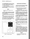
10.
Position
the
cast
bezel
and
implosion
shield
in
place
to
€nsure
that
there
is clearance
between
the
crt
face
and
the
bezel,
fl'he
bezel
must
bottom
on
the
front
casting.)
It. is
very
important
that
the
four
mounting
blocks
are
loose
enough
so
the
bezel
retaining
screws
can
be tightened
without
the
bezel
touching
the crt
face.
lf
not
the
crt
or
the
bezel
may crack
when
the
screws
are
tightened.
11.
Remove
the
bezel and
tighten
the mounting
block
screws
evenly
in
a cross
pattem
to approximatel!
8
in-lbs.
Make
sure
the crt
stays
centereO
in
tf,e
Utui
plastic
mounting
blocks
as
the screws
are
tightened.
12.
Replace
the bezel
and
implosion
shield,
recon-
nect
cables
to
their respective
board
connectors,
and
resolder
the
ground
lead
to its
terminal.
13.
Replace
crt
light
filter
and
snap-in
printed
bezel.
Repairing
the
Crt Trace
Rotation
Coil
The
trace
rotation
coil is
part
of
the
crt
assembly.
tf
the coil
is
damaged
beyond
repair,
the crt
with
the coil
must
be
replaced.
.lf
the
'finish"
(red)
lead
is
broken,
remove
the
tape
and
unwind
one
or
two tums
so it can
be respliced
and
solder€d
to
the
lead
wire.
Rewind
and
retape.
.lf
the
"start"
(black)
lead
is
broken
and
the lead is
too short
to
re-splice,
atempt
to fish
out
the
broken
end
so
one or
two turns
can
be
unwound,
re-splice
and
solder
to
the
lead;
then rewind
and
retape.
Front
Panel
Assembly
Removat
It
is
not
necessary
to
remove
the front
panel
assem-
bly
to replace
any
of
the
push
buttons. (Refer
to
Replacing
Front
Panel
pushbuttons,
that
follows
this
procedure.)
The crt
is
removed
with
the
front-panel
assembly,
1.
Set
the instrument
upright on
its rear
panel,
then
unscrew
and
remove
thg mounting
nuts
and washers
for
the RF
INPUT,
EXT
MIXER,
lst
Lo
oUTPUT. and
2nd
LO
OUTPUT connectors.
2.
Remove
the two screws
that hold
the
front
panel
to the RF
deck (center
and
left side).
6-23