


U10508
witt
ctock
first,
placing
a
high
at
the
Error
Amptifier,s
inverting
input.
This
iamps
it,"
"*ptiR",
ort-
put
low
untit
U1050A
switches
d
"iiort
time
tater.
U20508
resets
both
flip-flops
anO
tne
inner
toop
error
amprifier
wiil
stop
rampin!
untir
the
next
correction
cycle.
At
the
next
col-1clion
cycle,
the
error
amplifier
will
have
reduced
the VCO
freqfuency,
it
"i"for
reduc-
ing
the
mixer
difference
frequen.y.
fnl.-proceEs
con-
tinues
untit
the
two
signati
appfilO
to
the
lh".:"/F.r."q.uency
Detector
ar6
eOge
"6ilcioent,
mean-
ing
that
their
frequencies
and
ptras6
,"i"t.
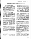
Error
Ampilfier.
The.Eror
Amptifier
boarct
(A50A4)
provides
the
inner
3F
oglgl
robp
error
amptifiErs,
enables
the
Strobe
Driver
(A5OA2),'and
generates
the
UP/DOWN
and
F
ERROR
signals.
,
The
inn-er
loop
amplifier
integrates
the
error
signals
from
the
Offset
Mixer
and
produJes
a cJriection
vottage
to
pull
the VCO
to a
frequency
that
is
synchronous
with
t!"
-r-[rl
signat.
Th€
Output
f"rii",
(A5OA3)
phasefrequency
dete-cJor
output
drives
integrating
diff€r.entiat
amptifier
U3075.
As
the
signais
driving
the
amplifier
continue
toward
one
directionl
the
output
con_
tinues
!o
change
the
oscillator
frequency
in
the
appropriate
direction.
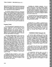
Zener
diode
VR2O6S
and
CRgO6g
glamp
tl:
jgel
loon
amptifier
output
io
$,"t
it stays
abovg
+5..
V.
This prevents
tonrrard
biasing
th€
VCO
varactor
diodes.
. - _4.
digital
control
circuits
consist
of
shift
register
U2025
and quad
anatog
switch
U2Og7.
Data
trom
the
microcomput.r
is
fed
seriaily.
via
th€
counter
board
cir-
cuits,
into.the.shiftregister,
then
transfer;;
to
the out-
put
fines
by
the
CONTROL
LATCH
signat.
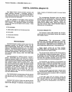
Tabte
T-21
lists
the
purpose
of
the output
lines.
rWith
OS low.
bwit
ot
tow.
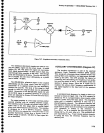
..-^fl"
outer
loop
amplifier
circuit
consists
of
amplifier
U2048
and
surrounding
components.
The
ERROd
sig_
nal
from
the
phase
Gate
Detector
and
Error
Amplifier
is
applied
through
LOOP
GAIN
adjustment
R0082
to
the
inverting
input
of
U2O4g.
The
signal
(ERROR)
is a
result
Theory
of
Operation
-
4g4ful4g4Ap
Service,
Vol.
1
of
the comparison
of
th€
1st
Local
Oscillator
frequency
and
the
nearest
muttiple
of
th€
STROBE
signat
trdm
tn6
Strobe
Driver
circuit.
The
ERROR
signat
varies
from
zero
to about
S00
kHz,
and
is
up
to 4
V
peakto-peak
in
amplitud€.
When
phase
lock
is
not
required,
data
into
U2OZ'
sets
output
e2
and
e4 tow
and
e3 high.
This
op"ni
the connection
between
pins
11
and
ld
of
U20g7and
the
connection
between pins
2
and
3.
STROBE
ENABLE
tine
to
th€
Strob€
Driver goes
high
and
dis-
ables
the strobe
pulse.
The
FM
coil
of
the
oscillator
is
opened
by U2A37
which
opens
the outer
toop.
.. lo
establish
phase
lock,
th€
microproc€ssor
sets
the lst
LO
near
the
d€sired
lock
point
and
loads
the
proper
N
number
into
the synthesizer.
The
S MHz
strobe
is
then
turned
on
(e4
and
e2 output
ot
U2025
set
high)
and
the
microprocessor
tunes
the 1st
LO
up or
down
750
kHz
either
side
of
the
desired
tock
point
Lt
a
10
Hz
rate.
When
the oscillator
frequency
crosses
the
desired
lock
point,
the
ERROR
frequency'is
reduced
to
a
dc voltage
which
resutts
in
U204g
puiling
the 1st
LO
in
th_e
direction
required
to maintain
a
consiant
frequency.
When
the
microprocessor
measures
the
lst
LO
fr€-
quency
and
finds
it
hetd
constant,
at
the
desired
fre_
quencyr
it
then
sets
Q3 output
ot
u2025low
to
reduce
the
bandwidth
of
the
phase
tock
toop.
The
UP and
DOWN
signats
alert
th€
microcomputer
that
the
drive
current
to th€
1st
Lo FM
coil
is
reaining
its
limit
in
holding
the
1st
LO in
phase
lock
The
microl
computer
then acts
to
bring
the 1st
LO
frequency
within
llt:-?pper
range.
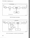
A
window
comparator,
ionsiittng
ot
U1015
and
thg
associated
components,
sens€s
when
U2048
has
approached
its
operating
limits.
When
the
microcomputer
causes
the
e2 signai
to close
the
path
from
U2048
to
the
FM
coil,
U2O4g
begins
to fumish
current
to the
coil
which
causes
the
1st
LO
to
track
the
stable
strobe
signal.
That
is,
each
time
the 1st
Lo
fre_
quency
drifts,
the
ERROR
signal
changes
and
U204g
shifts
the FM
coil
cunent
to
bring
th€ lst
LO
back
to its
original
frequency.
At
the
same
time,
the
microcom-
puter
causes
lines
el and
e5
to be low,
closing
the
contacts
that
connect
the output
of
u204g
to
the input
of
the
window
comparator
through
a
divider network.
Now,
as
the l
st
LO frequency
drifts,
the loop
amplifier
will
compensate
for
the
drift.
lf
the drift
is
excessive,
however,
V2048
will
approach
its
limits
and
wiil
be
unable
to furnish
any
more
current
to
the FM
coil.
_
Window
comparator
U101S
is
a
dual comparator
that senses
a
deviation
of *15
mV.
For
example,
if
a
frequency
shift
forces
U2049
to move
positive
enough
(approximately
3
V),
the
upper half
of
the comparator
conducts,
and
the Up line
goes
high.
This
triggers
the
service
request
circuits
on
the
Counter
board.
which
in
turn alerts
the
microcomputer
so
it
begins adjusting
the
TUNE
voltage
from
the
Center
Frequency
iontroi
cir-
cuits
to reduce
U204A output
to zero.
lf
the output
Tabte
7-21
U2025
OUTPUT
LINES
Llne
Q1
Q2
Q3
Q4
Q5
Low
Wide
windowa
Unlock
Narrow
loop
Strobe
disabled
Wide
windowb
Window
disabteda
Lock
Wide
loop
Strobe
enabled
Narrow
window
7-85