Theory
of Operalion
-
4g4A/4g4Ap
Service,
Vol.
1
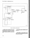
Low-order
DAC
U2055
tunes
approximately
+2.5mV
at
pin
1. and
its
gain
is adjusted
by
R1O2S.
l!e^
gain
oj
p-r_elmplifier
U1065
is
set
at
approximatety
10,000
by Rl056 and
the
5O
combination
of
R2O59
ana
R2060.
The combination
of
CR1056,
CRlO58,
RlO54,
and
R1059 limits
th€
gain
of
U1065 when
the output
exceeds
approximately
0.7
V in
either
direction.
Write-Back
Circuit
This
circuit
consists
of
comparator
Ul055
and
ena-
bling transistor Q1058. When
it is
necessary
to
do a
carry
between the
low-
and
high-order
DACs,
the circuit
is
put
into the hold
mode
by turning
ofr
Q1065.
U2060
is incremented one
bit
and
U2055 is reset to all
zeroEs_
The output of
u1065 is now
at something other
than
0 V. The
purpose
of
th6 following
approximation
rou-
tine is
to
get
output
of
U1065 as close
to 0
V
as
possi-
ble before
switching
the circuit
back into
track
rnode
by
tuming on Ql065.
Comparator
Ul055
det€cts
whether
the output of
U1065 is above
or
below
coarse
tune
ground.
The
instrument
rnicrocomputer
begins to exer-
cise
th€ low-order DAC bits one at
a
time
from
MSB
to
LSB. After each
bit is
turned
on,
U1055
ls enabted
by
turning off
Q1058.
lf
U1055 detects
that the
output
of
u1065
has crossed
0v, that
bit
is
turned
ofr
and
the
next lower
bit
is
turned
on.
This continues
through
all
12
bits
and when
completed,
th€ output of
U1065
should
be
close
to 0V. Transistor
Q1065
can
now
be
turned back
on without
causing
excessive
jumping
of
the
signal on
the screen.
-10
V
Reterence Buffer
The
circuit uses
the
voltage
reference developed on
the 1st
LO
Driver
board
as
a reference for
the DACs.
Differential amplifier
U20/5
receives
the
-10
V
refer-
ence
and
-1
0 V reference retum,
and
removes
eny
common-mode
signals
present.
Resistor
pairs
Rl048/R1049 and Rl050/R1051
are
matched
for
tem-
perature
coefficient
to minimize reference voltage
drift
over
temperature.
a
o
I
o
a
o
o
o
o
t
I
o
o
o
o
a
o
o
o
a
o
I
I
o
o
c
o
a
o
t
o
o
t
o
a
o
o
o
o
o
o
o
o
o
U1065
is
connected
to integrator
U2OT0
via
storage
gate
Q1065,
which
is
on
in
the
track mode.
Transistor
01065 is
turned off
any
time
a
DAC
is
being
tuned
to
allow
the
DAc
output
to settle
before
tuning
the
output
of
U2070.
lt
is also
turned
off
during
the
interval
when
a carry
from the
low-order
DAC
to the
high_order
DAC
occurs.
Transistor
Ql065
is controlled
by
e1061.
When
Q1061 is
on,
CR1064
is reverse-biased-
The
vol-
tage at
the
gate
of
e1065,
which
is
developed
by
R1064,
R1065,
R1067,
and
R1066,
is
near
O
V ana
Q1065 conducts.
When
e1061 is
off,
voltage
to
pinch
off
Q'l065
is
apptied
through
R1062
and
CR.t
064.
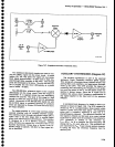
v2070
tracks
the
output
of
U1065 when
the circuit
is
in
the
track mode
and
serves
as
the
inverting
amplifier
in
ths fe€dback
system
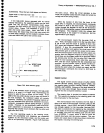
shown
in
Figure
7-26.
Normally
the
incoming signal
is
routed
through
R2067.
T;
improve
tl.e
slewing
rate
of
the integrator,
CRI
067 and
CR1069
conduct
and
connect
R1O6g
across
R2067
when
input
signals
over
1 V
are
present.
7-76


