


Theory of
Operation
-
494A1494Ap
Service,
Vot.
1
combination
with
multiptexer
U2020,
suppties
the
CON-
STANT data
to
U2030. Muttiptexer
U2A2O
is,
in
turn,
controlled
by address
bits
0, 1, and
2
to
provide
the
proper
constant
data
bit
to u2030.
Output Clrcults.
From
the U2030
verticat
display
register,
the
parallel
data output
is
applied
to
6-Oit
digital-to-analog
converter
U1035.
The
convefter
output
is
then applied
to
the output
storage/cursor
switch,
U20408,
through
a vector
generator
that
consists
of an
integrator
(Ul040
and
Cl03S) with
an
associated
feed-
back loop
sample-and-hotd
circuit.
Integrator
Ul040 has
a
time
constant
that
provides
a ramp
to tast
between
the
existing
sampl€
and
the
new
sample (that
is,
between sync
pulses).
Circuits
U2M0A
and
U2045 and
capacitor
C204S
make
up
a sample-and-hold
circuit
with
U2045 acting
as
an output
buffer.
From
U2045,
the output
current
through
resistor
R1036
subtracts
from
the
digitat-to-
analog converter
output
current
to modify
the
slop€ of
the
output
ramp.
The
output
of
the vector g€nerator
is
then
applied
to
switch
U20408.
U20408,
controlted
by
the MKR
(marker)
signal
from
the horizontal
section,
selects
between
the
recreated
video signal
from
u1040
and a
dc
(Peak/Average)
level from
buffer
U304S,
to
be
sent out
as
the v€rtical
signat.
The
dc level
is
displayed
only during rotrace
as
the PEAK/AVEBAGE
cursor.
Peak/Average
Level
Circults.
The
buffered
PEAK/AVG LEVEL
signal,
from
U3045,
is compared
with
the
sampled
Video
Fitter
Out signat,
from
U1045,
by
comparator
u2035A.
The
output
of
u2035A
is a
high
(1)
if
the video
Fitter
out signal
is
greater
than
the
PEAK/AVG
LEVEL,
or tow
if it
is tess.
This output
com-
mands
U2030, via
U4040C and
U4040D,
to send
peak
or average
data
to
the
output.
U40408,
C, and D are
used if the instrument
is
under
GPIB
control
to
select
one of
three
possible
modes;
peak,
Average,
or
front
panel
control
knob.
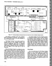
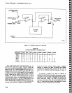
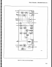
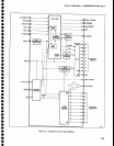
Horizontal
Section
(Diagram
26)
Figure 7-16
is a
block diagram
for
the Horizontal
Control lC
U5020. The
horizontal
analog
vottage
is
con-
verted
to
a current
table value
through
a
1O-bit
tracking
analog-to-digital converter
(adc),
which
consists
of
up/down
interlock
and
1O-bit
up/down
counter
in
U5020, and external
10-bit
digital-to-analog
converter
(clac)
U4040.
As
the
sweep
movss right, the
counter
Increments;
as
the
sweep retraces.
the
counter
decrements.
Each
time the
counter
increments,
it
generates
a new
X coor-
dinate
value
(the
dac input) and a
ST DIV
(start
ctivide)
signal to
start
the storage cycle. The increment
clock
is
the
SYNC
signal,
and
th€ decrement
clock is
the
basic
digital
storage clock
divided
by
two. When
the
Save
A
mode
is selected,
the
counter
skips every
other
binary
nUmber, so only
B coordinates
appsar
as
addresses.
A
state
machine
provides
the
horizontal
syst€m
intelligence.
This
circuit
determines
which
trace to write
on
the
screen,
determines
when
to
switch from
read
to
write,
generates
the B-A
coordination signals for verti-
cal
control lC
(on
th€
Vsrtical Digital
Storage board),
controls
the
g-bit
display
counter
incrementing,
and
proc€sses
requests for
the memory bus.
When an
external
device
€lects
to
read from or
write
to m€mory,
it allows
the BUs
REQ
(bus
r€quest) signal
to
go
high
to request
permission
from
the state
machine.
When
the
time
becomes
available,
the
state
machine
pulls
the BUS REQ line low, which signals
the
start of
a
request
cycle,
For
the
next eight clock
cycles,
the
internal multlpl€xer
output
lines are
in
th6
high-
impedance
(open)
tri-stats
modE.
The combination of
the up/down
interlock, 10-bit
up/down
regist€r,
9-bit display
counter,
and horizontal
display multipl€xer
constitute thg
primary
circuits
that
either write
to or read from m€mory. To
generate
X
values to be
written
into memory, the
circuits convert
the sweep voltage
to binary
form. These circuits also
count
the
sync
cycles
to
cause
the
external logic
to
read stored
data from
m€mory
and
produce
a vertical
signal
(Y
value)
for
each
corresponding
X value.
During acquisition
cycles, the
10-bit
up/down
counter, controlled
by the up/down
interloclq
operates
in a loop
with the external
10-bit
digital-to-analog
con-
verter. This allows
the counter to
acquire
the
equivalent
(X
value) of
a
sample
section
of
the
sw€ep
voltag€.
From
the
counter,
the
10-bit
output is applied to the
10-
bit up/down
register.
During
display cycles. the
g-bit
display counter counts sync
pulses
to
acquire the
x
value. Either the 1o-bit
up/down
register output
or
the
display
register
output is
applied
to the
horizontal
multi-
plexer
under control of
the
SELECT
signal
from the
State
Machine. From
the
multiplex€r,
th€
output is
applied
to ths m€morles
as an address.
o
a
o
?
I
o
)
o
o
t
I
I
I
o
o
o
o
o
o
o
o
o
C
a
o
o
o
o
o
o
t
o
)
o
I
o
I
o
o
o
o
t
I
I
7-44