


(b)
lf
the
-e1o-r-9cnr:
with
frequency
spans
greater
than
5
MHz/div,
ttre
t
si
t-O
is
iroO-
abty
defective.
(E)
(4)
lf
the
measured
and
calculated
currents
are
not
equal,
th€
problem
is
likely
in
the
final
stage
of
the LO
Driver.
(E)
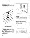
4.
Measure
the lst
LO
tuning
voltage
at
edge
con-
nector
47,
of
the
Center
Frequeniy
Conirot
boarO.
Ttris
voltage
shoutd
be within
200
mV
6t
tne tisteo
DAC
Set
value.
?. lffl".vottage
is
within
this
timit,
faiture
of
the
l
st
LO
Driver
board
is
indicated.
(E)
b. tf
th€ vottage
is
not
within
the
limit,
failure
of
the
Center
Frequency
Controt
board
is
inOicateO.
6y
TUNING
FATLURE
-
zND
LO
The
2nd
LO
is
set
by a
combination
hardware/software
loop.
There
are
two
distinct
hardware
blocks
in
the loop;
the
block
which
measurEs
the..oscillator
frequency
anO
tne
Uoct
wfrictr
sets
the
oscillator
to frequency.
The
micropro""".o,
closes
the
roop
by
d€termining
how
far
the oscillator
must
be
moved
to
bring
it
to
the
desired
frequency.
setting
is
an
iterative process
wherein
the
microprocesso,
counts
the
oscillator
frequency,
moves
it
as
needed,
and
counts
again.
The
error
message
ls
displayed
if
the
2nd
LO
is
not
set
to the
Oesiid
trequlncy
after
a
number
of iterations,
depending
on
instrument
lettings.
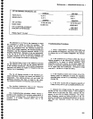
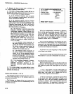
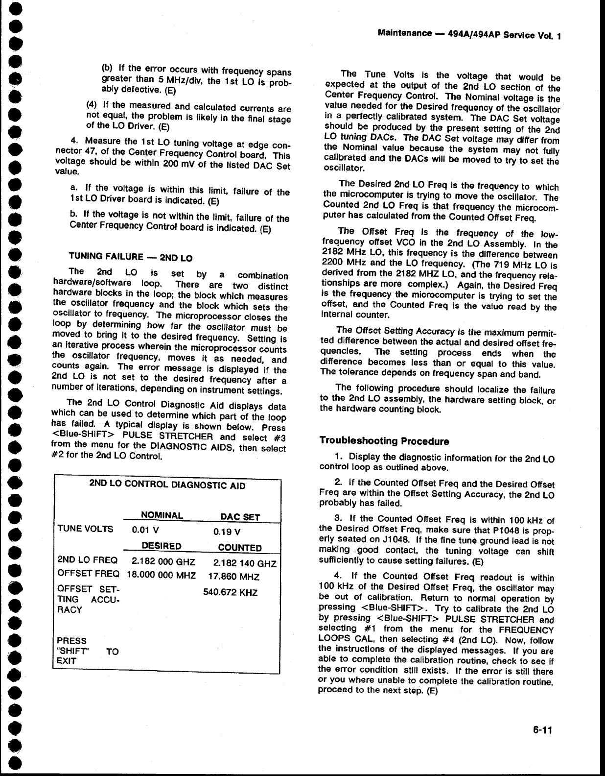
The
2nd
LO
Controt
Diagnostic
Aid
displays
data
which
can
be
used
to
deternrine
which
part
ot
t'tre
toop
has.
fait€d._11
typicat
disptay
is
snown
below.
press
<Blue-SHIFT>
PULSE
STRETCHER
and
setect
#3
from
the menu
for
the DIAGNOSTIC
AIDS,
then
select
#2tor
the 2nd
LO
Control.
Malntenance
_
4g4A/494Ap
Servlce
Vol.
1
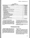
The
Tune
Volts
is
the
voltage
that
would
be
expected
at
the output
of
the
2nd
Lo section
of
the
Cent€r
Frequency
Control.
The
Nominal
voltage
is
the
value
needed
for
the
Desired
frequency
of
the
6scillator
in a
perfecfly
catibrat€d
system.
-me
beC
Set
vonale
should
be
produced
by the
present
seuing
of
the
2;d
LO
tuning
DACs.
The
DAC
Set
vottage
may
ditrer
trom
the Nominal
value
because_
the
system
may
not
fully
calibrated
and
the
DACs
witf
be
moved
to
tryto
set
th;
oscillator.
The
Desired
2nd
LO
Freq
is
the
frequency
to
which
the
microcomputer
is
trying
to
move
the osciitator.
The
Counted
2nd
LO Freq
is
that
frequency
the
microcom_
puter
has
calculated
from
the
Counted
Ofset
freq.
The
Offset
Freq
is
the
frequency
of
the
tow-
lr9^e-u9ncy
ofrset
VGO
in
the 2nd
LO Asiembly.
ln
the
2182
MHz
LO,
this frequ€ncy
is
the
difference
between
22OA
MHz
and
the
LO frequency.
Ftre
719
MHz
LO
is
derived
from
the
Z1g2
MHZ LO,
-ani
the frequency
reta-
tionships
are
more
complex.)
Again,
the
Desired
Freq
is--the
frequ€ncy
the
microcomputlr
is
trying
to set
the
offset,
and
the
Counted
Freq
is
the value
iead
by
the
internal
counter.
.If-|j,
Offset€etting
Accuracy
is
the
maximum
permat_
ted
difference
between
the actual
and
desired
otriet
fre-
quencies.
The
setting
process
ends
when
the
difference
beeomes
less
than
or
equal
to
this
value.
The
tolerance
depends
on frequency
span
and
band.
The
following
procedure
should
localize
the failure
to
the
2nd
LO
assembly,
the hardware
setting
block,
or
the
hardware
counting
block.
Troubleshooting
Procedure
1.
Display
the
diagnostic
information
for
the
2nd
LO
control
loop
as outlined
above.
2.
lf
the
Counted
Offset Freq
and
the
Desired
Offset
Freq
are
within
the
Offset
Setting
Accuracy,
the 2nd
LO
probably
has
failed.
3.
lf
the
Counted
Offset Freq
is within
100
kHz
of
the
Desired
Offset Freq,
make
sure
that
p1049
is
prop_
erly
seated
on
J1048.
lf
the fine
tune
ground
lead
is
not
making .good
contact,
the
tuning
voltage
can
shift
sufflciently
to
cause
setting
failures.
(E)
4.
lf
the
Counted
Offset
Freq
readout is
within
100
kHz
of
the Desired
Offset
Freq,
the oscillator
may
be out
of calibration.
Return
to
normal
operation
by
pressing
<Blue-SHIFT>.
Try
to calibrate
the 2nd
LO
by
pressing
<Blue-SHtFT>
PULSE
STRETCHER
and
selecting
#1 from
the menu
for
the
FREQUENCY
LOOPS
GAL, then setecting
#4
{2nd
LO).
Now,
foilow
the instructions
of
the displayed
messages.
lf
you
are
able
to
complete
the
calibration
routine,
check
to see
if
the
error
condition
sfllt exists.
lf
the error
is
stiil
there
or
you
where
unable
to
complete
the calibration
routine.
proceed
to
the next
step.
(E)
2ND
LO
CONTROL
DIAGNOSTTC
A'-
TUNE
VOLTS
O.O1
V
0.19
V
2ND
LO FREQ
2.182
OOO
GHZ
OFFSET
FREQ
18.OOO
OOO
MHZ
OFFSET
SET.
TING
ACCU.
RACY
2.182140
c4z
17.860
MHZ
540.672
KHZ
PRESS
"SHIFT'
EXIT
TO
6-11