


Specification
-
494At494Ap
Service,
Vol.
1
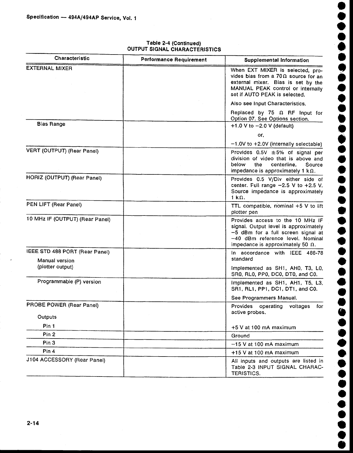
Characteristic
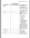
EXTERNAL
MIXER
Bias
Range
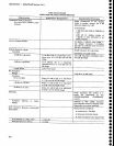
VERT (OUTPUT)
(Rear
Panet)
HORIZ
(OUTPUT)
(Rear
panet)
PEN LIFT
(Rear
Panel)
10
MHz lF (OUTPUT)
(Rear
Panet)
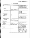
IEEE
STD
488
PORT (Rear
Panel)
Manual
version
(plotter
output)
Programmable
{P)
version
PROBE
POWER (Rear
Panet)
Outputs
Pin 1
Pin
2
Pin
3
Pin 4
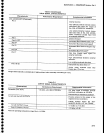
J104 ACCESSORY
(Rear
Panet)
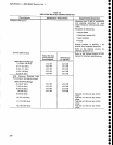
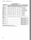
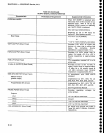
Table
2-4
(Continued)
OUTPUT
SIGNAL
CHARACTERISTICS
Supplemental
lnformation
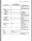
When
EXT MIXER
is
selected, pro-
vides
bias from
a
70f,) source
for
an
external
mixer. Bias
is set
by
the
MANUAL
PEAK
control
or internally
set if AUTO
PEAK
is
selected.
Also
see Input
Characteristics.
Replaced
by
75
O RF Input
for
ion
07. See Ootions
+1.0
V to
-2.0
V
(default)
or.
-1.0V
to
+2.0V
(internally
selectable)
Provides
0.5V
t5% of
signal
per
division of video
that
is above
and
below
the
centerline.
Source
impedance
is approximately
1 kO.
Provides
0.5
V/Div either
side ol
center. Full
range
-2.5
V
to
+2.5
V.
Source
impedance is approximately
1 ko.
TTL compatible,
nominal +5
V
to
lift
plotter pen
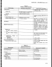
Provides
access to the 10 MHz lF
signal.
Output
level
is
approximately
-5
dBm for a
full screen signal
at
-40
dBm
reference
level.
Nominal
impedance
is
approximately
50 O.
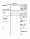
ln accordance with
IEEE 488-78
standard
lmplemented as
SHl, AHo, T3, L0,
SR0,
RL0, PP0,
DC0,
DT0, and
C0.
lmplemented as sH1, AH1,
T5, L3,
SR1,
RL1.
PP1,
DC1, DT1, and
C0.
See
Programmers Manual.
Provides operating voltages for
active
probes.
+5 V at'1
00
mA
maximum
Ground
-15
V at 100
mA
maximum
+'15
V
at
100 mA
maximum
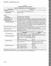
All inputs and outputs
are
listed in
Tab|e 2.3 INPUT SIGNAL
CHARAC.
TERISTICS.
o
o
o
I
I
I
t
o
o
o
o
I
o
o
O
o
o
I
l
t
I
o
o
o
o
o
I
o
I
t
o
o
o
o
o
t
o
I
o
o
o
a
o
f
2-14