


Performance
Check
procedure
-
4g4A/494Ap
Service
Vol.
1
^
b:
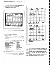
Check
frequency
response
from
10
kHz
to
10
MHz
(lower
end
of
Band
1).
-
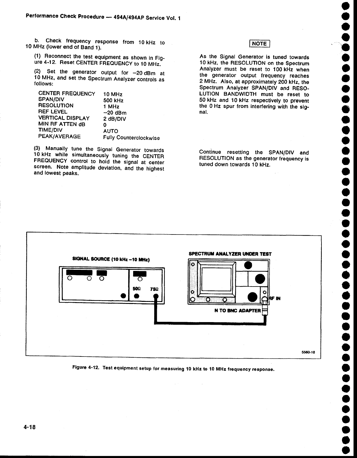
(1)
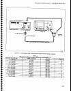
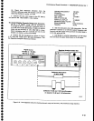
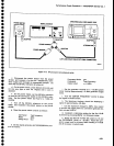
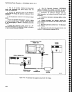
Reconnect
the_test
eguipment
as
shown
in Fig-
ure
4.12.
Reset
CENTER
FREQUENCY
Io 10
MHz.
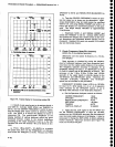
(2)
Set
the
generator
output
for
_20
dBm
at
10
MHz,
and set
the
Spectrum
Analyzer
controls
as
follows:
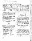
CENTER
FREQUENCY
10
MHz
SPAN/DIV
500 kHz
RESOLUTION
1
MHz
REF
LEVEL
-20
dBm
VERT|CAL
DTSPLAY
2
dBlDlV
MIN
RF
AfiEN
dB
O
TIME/DIV
AUTO
PEAK/AVERAGE
Fully
Counterclockwise
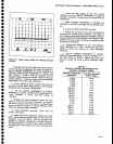
As
the
Signal
Generator is
tuned
towards
10 kHz,
the RESOLUTTON
on
the Spectrum
Analyzer
must
be reset
to 100
kHz
when
the
generator
output
frequency
reaches
2
MHa
Also,
at
approximatety
200 kHz,
the
Spectrum
Analyzer
SPAN/DIV
and
RESO-
LUTION
BANDWIDTH
must
be reset
to
50 kHz and
10
kHz
respectively
to
prevent
the
0
Hz
spur
from interfering
with
the sig-
nal.
Continue
resetting
the
SpAN/DlV
and
RESOLUTION
as
the
generator
frequency
is
luned
down
towards 10
kHz.
o
o
o
o
a
o
o
I
o
a
o
a
o
o
O
a
o
a
o
O
o
I
a
o
o
o
a
a
a
I
a
I
o
o
o
o
a
a
o
o
o
o
o
a
(3)
Manually
tune
the
Signal
Generator
towards
10kHz
while
simultaneousty
tuning
the
CENTER
FREQUENCY
control
to hold
the
signal
at
center
screen.
Note
amplitude
deviation,
and
the
highest
and
lowest peaks.
SPECTRT'T
AIIALYZER
UIIDER TEST
SlOllAL
SOT
RC€
(10
kltr
-.t0
lrtltr)
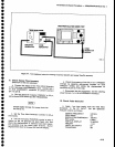
Figure
4-12.
Test
equipment
setup
for
measuring
10 kHz to 10
MHz frequency
response,
4-18