


ct66.t-14
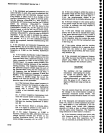
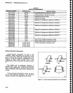
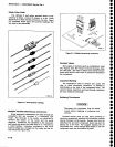
Figure
6-2.
Diode polartty
marklngs.
Maintenance
-
494A/494Ap
Servtce
Vot.
1
Diode
Color
Code
The
cathode
of
each glass
encased
diode
is
indi-
gated
by a stripe,
a
series
of
stripes,
or
a
dot.
Some
diodes
have
a
diode symbol
printed
on
one
side.
Figure
6-2 illustrates
diode
types
Lnd potarity
markings'that
are
used
in
this
instrument.
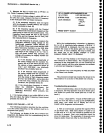
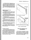
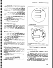
Multiple
Terminal (Harmonica)
Connectors
Som€ int€rcircuit
connections
are
made
through
pin
connectors
that are
mounted
in a
harmonica-
type
holder.
The
terminals
in
the
holder,
are
identified
ty
numbers
that appear
on
the
holder
and
the circuit
diagrams.
Connectors
are
identified
on
the schematic
and
board
with
either
the
prefix
letter
p
or
J
followed
by
a circuit
number.
Connector
orientation
to the
circuit
board
ls keyed
by a
triangle
on
the holder
and
the cir_
cuit
board
(see
Figure
6-3).
6-18
Flgure
6-3. Multpln
(harmonlca)
conneciors.
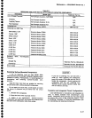
Resistor
Values
Many
types
of
resistors (such
as composition,
metal
film,
tapped,
thick film resistor
network
package,
plate,
etc.) are
used. The value
is
either
color coded
in accor-
dance with
the
EIA color code,
or
printed
on
the
body
of
the
component.
Capacitor
Marking
The capacitance
value
of ceramic
disc,
plate,
and
slug, or
small electrolytic
capacitors,
is marked
in
microfarads
on
the
side
of
the
component
body. The
ceramic
tubular capacitors
and
feed-through
capacitors
are
color coded
in
picofarads.
Soldering
Techniques
Disconnect
the
instrument
from
its
power
source
before
replacing
or soldering com-
ponents.
Extreme
caution must
be
used when removing or
replacing
components
because
the instrument
contains
several multilayer
circuit
boards. Excess heat from
the
soldering iron
and bent
component
leads may
pull
the
plating
out
of the
hole.
We suggest clipping
the
old
component
free. Leave
enough
lead length so
the
new
component leads
can
be soldered
in
place.
o
o
o
o
a
o
o
o
o
o
I
o
I
t
o
o
o
o
I
o
o
o
a
a
I
o
a
o
)
a
a
o
o
o
o
I
o
o
o
o
c
a
o
o
ffi.
-
\
(x)95-11