EDIT Menu
AWG2021 User Manual
3 Ć133
(5) L
ąąValue
Shows the data value (Value) indicated by a real number and
the time or point count (L) for the current position of the lower
line cursor.
(6) Upper Line Cursor The line that is brightly highlighted by the upper line cursor is
active.
(7) MARKER (1,2) Binary display of the state of Marker 1 or 2 for the waveform
point or time.
(8) Lower Line Cursor The line cursor enclosed in a frame ([]) is inactive.
(9) Point Index or Time Shows the waveform point or time. The units are set with the
Setting item in the bottom menu.
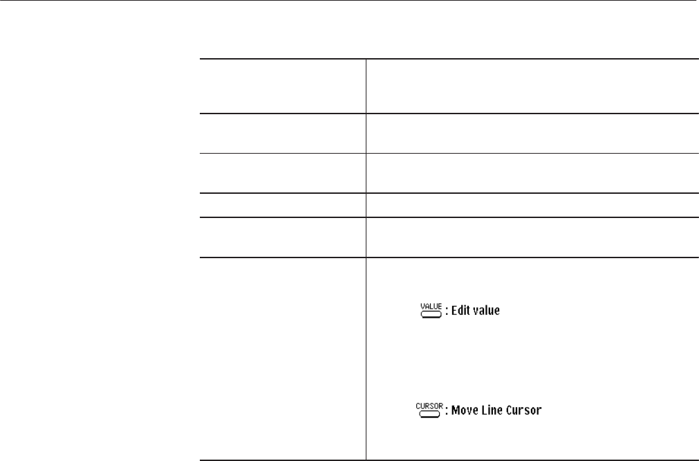
(10) Button Operations This area shows how the front panel buttons operate in this
menu.
When the VALUE button is pressed, a block cursor appears
within the inverted display cursor and the numeric keys can be
used to input the data. Pressing an arrow button (z/!)
moves the block cursor left/right.
When the CURSOR button is pressed, the line cursor can be
moved.
Before waveform data is created, you must use the Setting item in the side menu
to set the environment for editing. Apart from the cardinal number settings, the
procedure for setting values is the same as for the graphic display. See “Setting
for the Waveform to be Edited” for a description of the graphic display.
Setting a Cardinal Number. Use Radix... to set a cardinal number to display
waveform data in a table format. Waveform data can be displayed in numeric
form as Binary, Hexadecimal or Real numbers.
When Radix... is selected, the following items appear in the sub-menu:
Binary
Hexadecimal
Real
Go Back
The description of these cardinal numbers is given below.
Binary 12-bit waveform data is created using the 0 or 1 numeric
keys.
Settings for the Waveform
to be Edited
