


Appendix A: Options and Accessories
AWG2021 User Manual
AĆ3
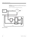
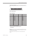
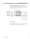
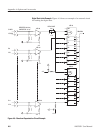
Output Connector Configuration. Figure A-2 shows the shape and pin number
location of the output connector, and Table A-1 shows the output signal for each
pin.
35
1
34
68
Figure AĆ2: Output Connector
Table AĆ1: Output Signal
Pin Number Signal Pin Number Signal
6 ~CLOCK 39 CLOCK
14 ~Data Bit 0 47 Data Bit 0
12 ~Data Bit 1 45 Data Bit 1
10 ~Data Bit 2 43 Data Bit 2
8 ~Data Bit 3 41 Data Bit 3
16 ~Data Bit 4 49 Data Bit 4
20 ~Data Bit 5 53 Data Bit 5
22 ~Data Bit 6 55 Data Bit 6
18 ~Data Bit 7 51 Data Bit 7
30 ~Data Bit 8 63 Data Bit 8
28 ~Data Bit 9 61 Data Bit 9
26 ~Data Bit 10 59 Data Bit 10
24 ~Data Bit 11 57 Data Bit 11
Pins 4, 33, 34, 37, 67, and 68 are not connected.
Pins that are not mentioned are connected to chassis ground.
~ = active low signal
Operation. Operation is the same as for the basic instrument. When a waveform
is not being output, the waveform’s initial data may be output to the connector.
At this time, no clock is generated.
When starting the waveform output, the clock is generated and the data is
updated.