


Appendix E: Functional Operation Summary
EĆ4
AWG2021 User Manual
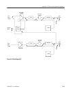
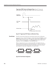
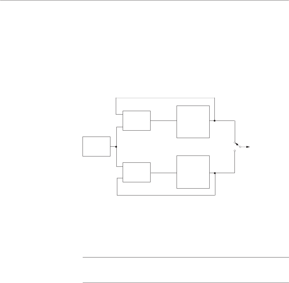
The oscillator for internal clock use is normally a PLL (phase lock loop) type. It
uses a liquid crystal oscillator that provides a stable 12.8 MHz signal. The clock
oscillates from 250 MHz to 125 MHz. The minimum frequency resolution is 5
kHz and the frequency can be set with 4-digit precision.
Frequencies under 125 MHz can be obtained by changing the frequency division
of the clock divider. In this way, a clock frequency as low as 10 Hz is possible.
Figure E-3 shows the configuration of the clock oscillator.
12.8 MHz
Crystal
Oscillator
Phase
Detector
Phase
Detector
Voltage
Controlled
Oscillator
(High)
Voltage
Controlled
Oscillator
(Low)
Clock Output
Figure EĆ3: Clock Oscillator Configuration
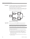
This block controls the AWG2021 MODE menu operating (output) mode.
First, select the clock source. Normally, the clock oscillator output is used.
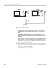
NOTE. The external clock input and output are used when more than 2 channels
must be synchronized with the clock. Also, the external clock input can be
connected to another oscillator, for example, a frequency sweep signal generator.
Clock Operations by Operation Mode. There are four output operation modes:
H Cont Mode. The clock is sent to the clock divider regardless of the trigger.
H Trggered and Burst Mode. When the (External or Manual) trigger is
generated, the clock is sent to the clock divider to obtain an output signal
synchronized with the trigger. If the sync signal is set to Start, a pulse of
about 100 ns width is output.
H Gated Mode. While the gate signal is True, the clock is sent continuously to
the CH1 clock divider.
Clock Oscillator
Trigger Control