Operating Examples
AWG2021 User Manual
2 Ć35
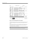
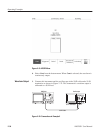
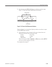
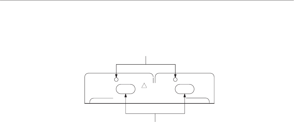
2. Press the front panel CH1 On/Off button to switch on waveform output.
Figure 2 -23 shows the channel On/Off button and indicator.
CH 1
25Vp–p MAX OPEN CIRCUIT FROM 50 W
On/Off Indicators
On/Off Buttons
CH 2
!
DO NOT
APPLY EXT SIGNAL
Figure 2 Ć23: Channel On/Off Buttons and Indicators
When the Channel is on, the indicator lights up and the set waveform is output
from the CH1 output connector.
3. Set the parameters for the connected oscilloscope as shown below and
display the waveform on the oscilloscope screen.
Volt/Div. 200 mV/Div.
Time/Div. 1 ms/Div.
Trigger Mode Auto
When you change the Clock, Amplitude, or Offset items with the SETUP
menu, the waveform changes in real time.
This completes the example 2.


