MODE Menu
AWG2021 User Manual
3 Ć237
applied to the TRIGGER INPUT connector or by pressing the front panel
MANUAL button.
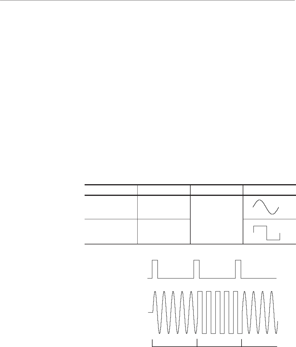
In this mode, the first waveform is output over and over again for each channel
when a trigger signal is received. When the next trigger signal is received, output
of the first waveform stops after the end point of that waveform and then the
second waveform is output in the same manner. The next waveform is not started
at the moment a trigger is received, but rather at the completion of the previous
waveform.
In this way, waveforms are output for each channel one by one in sequence each
time a trigger signal is received. When a trigger signal is received while output
of the last waveform is in progress, the output stops at the end point of that
waveform and then the process begins again from output of the first waveform.
Each channel operates independently according to the number of waveform
points.
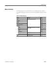
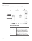
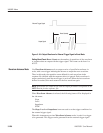
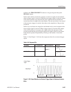
Table 3–15 and Figure 3 -165 show the output waveform for an external trigger
signal.
Table 3Ć16: Sequence File
File Name No. of Repetitions Output Conditions Waveform
WAVE1.WFM 2
Amplitude 2 V
Offset 0 V
WAVE2.WFM 2
External Trigger
Signal
Output Signal
-1 V
1V
WAVE1.WFM WAVE2.WFM WAVE1.WFM
Figure 3 Ć165: Output Waveform for External Trigger Signal in Waveform Advance
Mode


