Function Waveform Generator Mode
AWG2021 User Manual
3 Ć297
Function Generator Menu Display
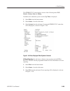
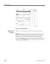
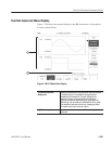
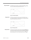
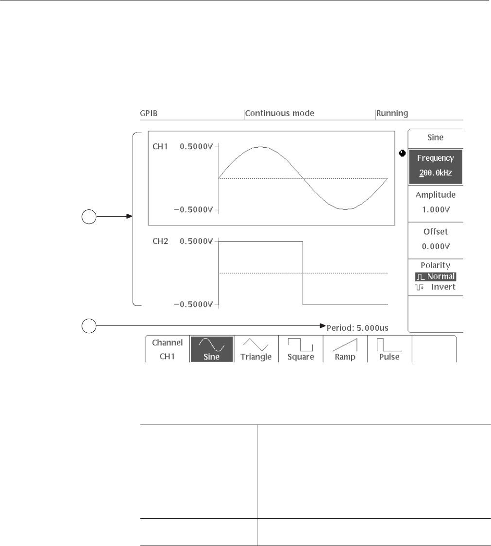
Figure 3 -200 shows the general display for the FG mode menu. A description
for each callout follows.
1
2
Figure 3 Ć200: FG Mode Menu Display
(1) Channel waveform
display area
Displays the waveform set for that channel. When the channel
is enclosed by a box, it is possible to change the output
parameters for that waveform. The peak voltage for the
waveform is shown on the vertical axis to the left of the
waveform; this value is determined by the amplitude or the
offset setting. The horizontal axis (the dotted line in the center
of the waveform) indicates the zero line; changing the offset
will cause the zero line to move up or down.
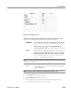
(2) Waveform period Shows the period for the waveforms. This value is applied to all
waveforms.


