Appendix E: Functional Operation Summary
AWG2021 User Manual
EĆ5
AWG2021 Parallel Operation. When more than two channel outputs are needed,
connect as shown below.
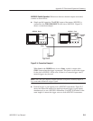
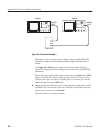
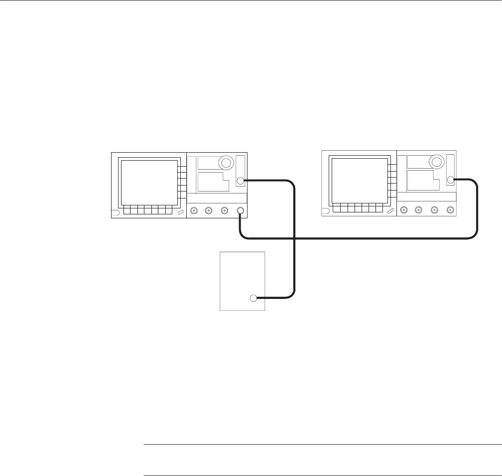
H Simple parallel operation. The SYNC output of the master AWG2021 is
connected to the TRIGGER INPUT of the slave AWG2021. Figure E-4
shows a connection example.
AWG2021
AWG2021
TRIGGER
INPUT
TRIGGER
INPUT
Slave
OUT
SYNC
Output
Trigger Source
Master
Figure EĆ4: Connection Example 1
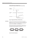
When Sync in the MODE menu is set to Start, a pulse is output at the
SYNC output when the trigger is generated. This pulse is used as the trigger
for the slave AWG2021. In this case, if there is no external trigger source,
manual triggers may be used.
NOTE. Since the sync output is output when the waveform is actually output, it
lags somewhat behind the trigger signal.
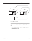
H External trigger or gate signals to two AWG2021 instruments. Figure E-5
shows the connection method for applying external trigger or gate signals
simultaneously to two AWG2021 instruments. Use BNC 50 W cables of the
same length to connect the trigger source to both AWG2021 instruments.


