


Appendix C: Performance Verification
CĆ38
AWG2021 User Manual
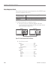
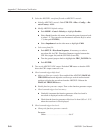
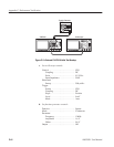
4. Check rear-panel CH1 MARKER Out 2 pulse amplitude:
a. Check CH1 MARKER 2 OUT pulse amplitude:
H Remove the coaxial cable from the AWG2021 front-panel CH1
MARKER 1 connector and connect it through the SMA-BNC
adapter to the rear-panel CH1 MARKER 2 OUT connector.
H Check that the pulse amplitude of the displayed waveform is from
2.250 V
p-p
to 2.625 V
p-p
.
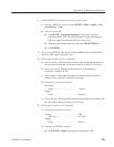
5. Check Option 02: If the AWG2021 has a second channel, repeat this entire
test, selecting the AWG2021 waveform and setting controls for CH2 and
checking:
H Rear-panel CH2 SYNC Out pulse amplitude
H Rear-panel CH2 MARKER 1 pulse amplitude
H Rear-panel CH2 MARKER 2 pulse amplitude
6. End procedure: Disconnect the oscilloscope.
External Trigger Level Accuracy Check
This procedure checks the external trigger level accuracy of the AWG2021.
Electrical
Characteristic Checked
Auxiliary Inputs, Trigger, Accuracy, on pageĂBĆ9.
Equipment Required Two 50ĂW coaxial cables, a function generator, and an
oscilloscope.
Prerequisites The AWG2021 meets the prerequisites listed on page CĆ5.
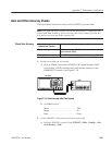
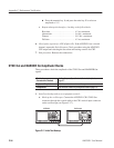
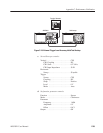
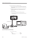
1. Install test hookup and set test equipment controls:
a. Hook up oscilloscope: Connect the AWG2021 CH1 output through a
coaxial cable to the oscilloscope CH1 vertical input.
b. Hook up function generator: Connect the AWG2021 TRIGGER INPUT
through a coaxial cable to the function generator output (see Fig-
ure C-18).