


Appendix C: Performance Verification
CĆ36
AWG2021 User Manual
H Press the numeric key 1, and press the units key V to select an
amplitude of 1 V.
c. Repeat substeps 4a through e, checking to the follow limits:
Rise time 4.2 ns, maximum. . . . . . . . . . . . . . . . . . . . . . . .
Aberrations 0.4 div., maximum. . . . . . . . . . . . . . . . . . . . . .
Flatness 0.15 div., maximum. . . . . . . . . . . . . . . . . . . . . . . . .
Fall time 4.2 ns, maximum. . . . . . . . . . . . . . . . . . . . . . . .
6. Check pulse response for CH2 (Option 02): If the AWG2021 has a second
channel, repeat this Pulse Response Check procedure using the AWG2021
CH2 output and selecting the waveform and setting controls for CH2.
7. End procedure: Remove the connections.
SYNC Out and MARKER Out Amplitude Checks
These procedures check the amplitude of the SYNC Out and MARKER Out
signals.
Electrical
Characteristic Checked
Auxiliary Outputs, Sync, Marker 1, Marker 2, Amplitude, on
pageĂBĆ7.
Equipment Required A 50ĂW coaxial cable and an oscilloscope.
Prerequisites The AWG2021 meets the prerequisites listed on page CĆ5.
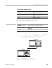
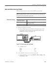
1. Install test hookup and set test equipment controls:
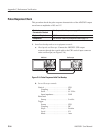
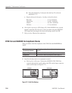
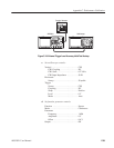
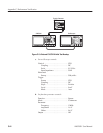
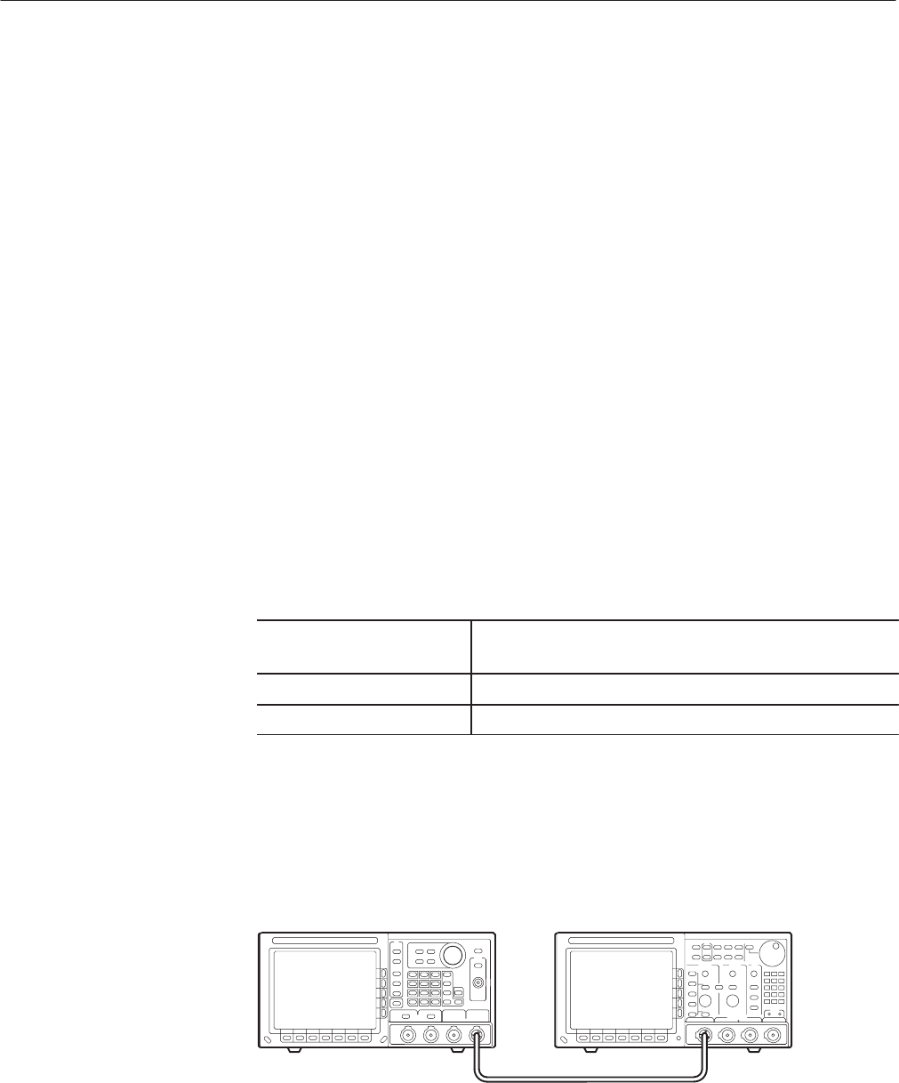
a. Hook up the oscilloscope: Connect the AWG2021 CH1 SYNC Out
connector through the coaxial cable to the CH1 vertical input connector
on the oscilloscope (see Figure C-17).
OscilloscopeAWG2021
540
TDS
AWG2021
Figure CĆ17: Initial Test Hookup