


AWG2021 User Manual
3 Ć295
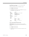
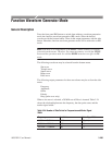
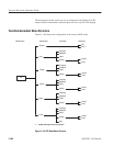
Function Waveform Generator Mode
General Description
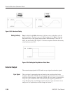
Press the front panel F.G button to switch from arbitrary waveform generation
mode into function waveform generation (FG) mode. Select the desired
waveform with the bottom button. Then set the output parameters with the side
button. Hereafter, function waveform generator mode will be referred to as FG
mode.
NOTE. FG mode is an independent of the MENU column arbitrary waveform
generation mode menus. Therefore, the output parameters set with the SETUP
menu and the operation mode set with the MODE menu have no effect in FG
mode.
The following waveforms may be selected from the bottom menu:
Sine wave
Triangle wave
Square wave
Ramp wave
Pulse wave
The following output parameters for these waveforms may be set from the side
menu:
Frequency
Amplitude
Offset
Polarity
Duty (pulse wave only)
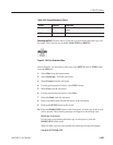
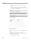
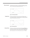
When a sine wave is selected, a 20 MHz cut-off filter is inserted. Table 3-24
shows the relationship between the frequency, the data point count, and the
marker signal width.
Table 3Ć24: Number of Data Points for Frequencies and Marker Signal
Width
Frequency Data Points Marker Signal Width
10.00 Hz 25.00 kHz 10000 200(points)
25.01 kHz 250.0 kHz 1000 ă20
250.1 kHz 2.500 MHz 100 ăă2