Appendix A: Options and Accessories
AWG2021 User Manual
AĆ5
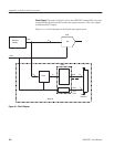
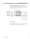
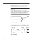
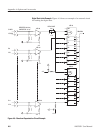
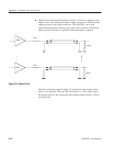
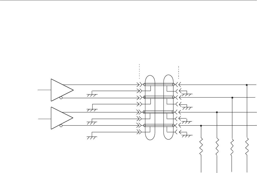
Output Circuit and Output Waveform. The ECL buffer (10E116) output is
connected directly to the output connector. When used, these signals must be
terminated to –2 V with a 50 W resistor at the receiving side (user side). If this
termination resistor is missing, the signals do not appear at the output connector.
The same is true for the clock output (see Figure A-4).
D0
D0
D1
D1
p-47
p-48
p-14
p-13
p-45
p-46
p-12
p-11
Connector Cable
-2V -2V -2V -2V
Figure AĆ4: Output Circuit
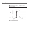
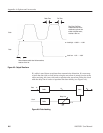
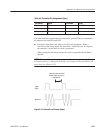
The data output signal skew is held to 1 ns max. The rise and fall time depend on
the buffer ICs, but neither is greater than 1 ns (see Figure A-5). Neither of these
specifications includes cables; it is specified at the output connector.


