


ISDN Compatibility
374 ◆ Features Aspire Software Manual
Basic Rate Interface (BRI)
Your system also provides compatibility with ISDN Basic Rate (BRI) services, including:
● Basic BRI Call Control (BCC)
● Point-to-Point BRI Terminal Connection (no daisy-chaining)
● Multipoint BRI Terminal Connection (daisy-chaining)
● S-Bus (allows BRI PCB's to be used as either a trunk or station interface)
BRI services require the installation of BRI Interface PCBs (2BRIU P/N 0891050 (Aspire S) or
0891006 (Aspire), 4BRIU P/N 0891007, 8BRIU, P/N 0891008). Each 2BRI Interface PCB has two
BRI circuits. The 4BRI Interface PCB has four BRI circuits, while the 8BRI has eight BRI circuits.
The BRI Interface PCBs use a single universal slot.
● 2BRI (Aspire S: P/N 0891050, Aspire: P/N 0891006):
● Provides 30 BRI circuits and 60 BRI channels.
Each PCB takes up 8 ports. If any circuits set for T-Bus, the next set of 4 trunk ports
are used. If any circuits are set up for S-Bus, the next 4 station ports are used.
● 4BRI PCB (P/N 0891007)
● Provides 60 BRI circuits and 120 BRI channels.
Each PCB takes up 16 ports. If any circuits set for T-Bus, the next set of 8 trunk ports
are used. If any circuits are set up for S-Bus, the next 8 station ports are used.
● 8BRI PCB (P/N 0891008)
● When used as T-Bus, provides 96 BRI circuits and 192 BRI channels. When used as S-
Bus, 120 BRI circuits and 240 S-Bus stations ports are provided.
Each PCB takes up 32 ports. If any circuits set for T-Bus, the next set of 16 trunk ports
are used. If any circuits are set up for S-Bus, the next 16 station ports are used.
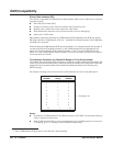
Each BRI Has Two TEI’s
For each BRI line, two different TEI’s will be assigned to two different SPID’s.
The two different SPID’s for each BRI line, will be related to different trunk logical port numbers.
One BRI provides two trunk logical ports when it is connected to a CO line. Each SPID is assigned
to a different TEI. This relationship is made in the initialization of the BRI line when it is connected
to the CO.
This relationship between SPID and TEI’s are created as follows.
LOGICAL-PORT-NUMBER + 0 = SPID-1
LOGICAL-PORT-NUMBER + 1 = SPID-2
When using the SMDR reports for BRI, all incoming BRI calls will be displayed under the CLASS
column as “IVIN”.
Automatic Data Link Failure Recovery
If a data link error is detected by the BRI PCB, the system will try to recover the data link and send the
SPID to the central office. To provide this enhancement, the BRI PCB must be able to indicate to the sys-
tem when a data link error has occurred.
Note: In addition to BRI Interface PCBs, BRI Services require the installation of NT1 Network
Terminators and interconnecting cabling.