


104 SA-1110 Developer’s Manual
System Control Module
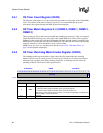
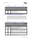
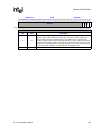
Next, software should examine the power manager sleep status register (PSSR) to determine why it
was in sleep. This register has bits to indicate whether a VDD_FAULT, BATT_FAULT, or force
sleep bit has been asserted since the register was last cleared. It is possible for multiple bits to be set
in this register.
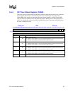
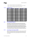
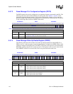
Also, the SA-1110 provides the power manager scratch pad register (PSPR) for saving any general
processor state during sleep. This register may be written by the processor and the contents will
survive sleep mode. The bits in this register are not explicitly used by the SA-1110, but may be
used by software to index into ROM space to retrieve memory controller configuration, for
example.
Note: The nRESET pin must not be asserted during sleep mode if the DRAM contents are to be
preserved. The assertion and subsequent negation of nRESET during sleep mode causes the
SA-1110 to clear the FS bit in the force sleep register, assert PWR_EN, time the PLL lock
sequence, and subsequently negate the internal reset signal. This causes the SA-1110 to perform a
normal boot sequence because all information about the previous sleep state is lost.
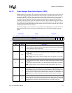
9.5.3.7 Reviving the DRAMs from Self-Refresh Mode
Because the DRAMs are placed in self refresh prior to the sleep mode shutdown, their contents are
preserved during sleep. After exiting sleep, software must reconfigure the DRAM control registers,
which lost power during sleep mode, and then take the DRAMs out of self-refresh mode. Clearing
the DRAM hold (DH) bit in the power management status register (PMSR) will cause the
nRAS/nSDCS[3:0] and nCAS/DQM[3:0] pins to return to the negated state (high) in preparation
for a DRAM access.
In addition to clearing PMSR:DH, bringing SDRAM out of self-refresh requires that the SDRAM
controller be transitioned from a self-refresh and clock-stop state to an idle state. This involves
successive writes to the DRAM Refresh Control Register (MDREFR) to set one or both SDRAM
clock run bits (K1RUN and/or K2RUN) and to set the SDRAM clock enable bit (E1PIN). See the
Chapter 10, “Memory and PC-Card Control Module” for details.
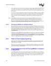
9.5.4 Notes on Power Supply Sequencing
On the SA-1110, as on the SA-110, it is important that VDDX (3.3 V nominal) power-up occur
before VDDI (1.5 V nominal). One approach to ensuring this sequencing is to power the 1.5-V
supply using the 3.3-V supply.
On the SA-1110, a second simple option is available. If the PWR_EN output is used to enable the
1.5-V supply, the SA-1110 will enforce the required sequencing by holding PWR_EN deasserted
until the 3.3-V supply is sufficiently high.
9.5.5 Assumed Behavior of an Intel
®
StrongARM SA-1110 System
in Sleep Mode
The assumed model of an SA-1110 system in sleep mode is one in which the system is relatively
quiet. In particular, there should be no gratuitous switching on of the SA-1110 input pins. Although
there will be some switching in GPIOs to bring the processor out of sleep and potentially on the
VDD_FAULT and BATT_FAULT pins, the switching is a low-frequency activity and usually
brings the SA-1110 out of sleep mode.