


30 SA-1110 Developer’s Manual
Functional Description
– Twenty-eight general-purpose I/Os (GPIO)
– An interrupt controller
– A power-management controller that handles the transitions in and out of sleep and idle
modes
– A reset controller that handles the various reset sources on the processor
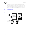
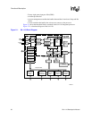
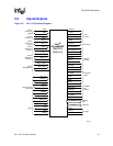
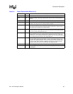
Figure 2-1 shows the functional blocks contained in the SA-1110 integrated processor.
Figure 2-2 is a functional diagram of the SA-1110.
Figure 2-1. SA-1110 Block Diagram
A6608-01
Serial
Channel 0
UDC
Serial
Channel 2
IrDA
Serial
Channel 3
UART
Serial
Channel 1
GPCLK/UART
Bridge
DMA
Controller
JTAG
and
Misc
Test
Read
Buffer
Write
Buffer
LCD
Controller
Intel
®
StrongARM
*
SA-1110
Microprocessor
IMMU
DMMU
32.768
KHz
3.686
MHz
OSC
OSC
PLL2
PLL1
Icache
(16 Kbytes)
Dcache
(8 Kbytes)
Peripheral Bus
System Bus
Load/Store Data
RTC
Minicache
PC
Instructions
Addr
Memory and
PCMCIA
Control Module
ARM
*
SA-1
Core
OS Timer
General-
Purpose I/O
Interrupt
Controller
Power
Management
Reset
Controller
Serial
Channel 4
CODEC