


SA-1110 Developer’s Manual 295
Peripheral Control Module
11.9 Serial Port 1 – GPCLK/UART
Serial port 1 is a combination general-purpose clock controller (GPCLK) and universal
asynchronous receiver/transmitter (UART) serial controller. The user can configure it to perform
one of the two functions, but operation of both modes using serial port 1’s pins cannot occur
simultaneously However, the peripheral pin control (PPC) unit can be configured to take control of
two GPIO pins and use them for UART transmission, while serial port 1’s pins are used for
GPCLK operation. See the Section 11.13, “Peripheral Pin Controller (PPC)” on page 11-382 for a
description of how the PPC is configured to allow use of both the GPCLK and UART.
Used as a GPCLK controller, serial port 1 can output a clock on GPIO pin 16 with a frequency in
the range of 900 Hz to 3.6864 MHz.
Used as a UART, serial port 1 is identical to serial port 3. It supports most of the functionality of
the 16C550 protocol including 7 and 8 bits of data (odd, even, or no parity), one start bit, either one
or two stop bits, and transmits a continuous break signal. An interrupt is generated when a framing,
parity, or receiver overrun error is present within the bottom four entries of the receive FIFO, when
the transmit FIFO is half-empty or the receive FIFO is one- to two-thirds full, when a begin and
end of break is detected on the receiver, and when the receive FIFO is partially full and the receiver
is idle for three or more frame periods. Because programming and operation of serial port 1 as a
UART is identical to serial port 3, see the Section 11.11, “Serial Port 3 – UART” on page 11-325
for a complete description of using serial port 1 in UART mode.
The external pins dedicated to this interface are TXD1 and RXD1. If serial transmission is not
required and both the GPCLK and UART are disabled, control of these pins is given to the
peripheral pin control (PPC) unit for use as general-purpose input/output pins (noninterruptible).
See the Section 11.13, “Peripheral Pin Controller (PPC)” on page 11-382.
Modem control signals (RTS, CTS, DTR, and DSR) are not provided in this block but can be
implemented using the general-purpose I/O port (GPIO) pins described in the Chapter 9, “System
Control Module”.
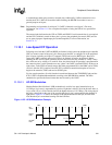
11.9.1 GPCLK Operation
Following reset, both the GPCLK and UART are disabled. This causes the Peripheral Pin
Controller (PPC) to assume control of the port’s pins. Reset causes the PPC to configure all of the
peripheral pins as inputs, including serial port 1’s transmit (TXD1) and receive (RXD1) pins.
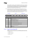
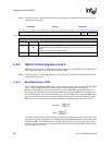
0h8000 001c UDCD0 UDC Endpoint 0 data register
0h8000 0020 UDCWC UDC Endpoint 0 write count register
0h8000 0024 — Reserved
0h8000 0028 UDCDR UDC transmit/receive data register (FIFOs)
0h8000 002c — Reserved
0h8000 0030 UDCSR UDC status/interrupt register
Table 11-14. SA-1110 UDC Control, Data, and Status Register Locations
Address Name Description