


208 SA-1110 Developer’s Manual
Peripheral Control Module
11.4 Peripheral Pins
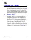
Each peripheral has a number of dedicated pins with which to communicate to off-chip devices.
The six peripherals of the SA-1110 use a total of 24 pins: the LCD uses twelve pins; serial port 4
four pins; and serial port 0 through 3 each use two pins. Many applications may not require the use
of all six of the SA-1110’s peripherals. To provide maximum flexibility, the pins associated with
any unused peripheral (except serial port 0) can be used as general-purpose digital input/output
pins that are noninterruptible. When a peripheral is disabled, the peripheral pin controller (PPC)
automatically takes control of the peripheral’s pin direction and pin state. A user can sample input
pin state by reading the PPC pin state register (PPSR) and control the state of an output pin by
writing to it. Pin direction is established by configuring the PPC pin direction register (PPDR).
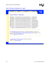
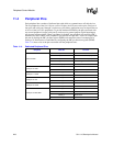
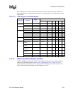
Table 11-4 shows a list of the pins associated with the peripheral units.
.
Table 11-4. Dedicated Peripheral Pins
Peripheral GPIO Pin Function
LCD Controller
L_PCLK Pixel clock
L_LCLK Line clock/horizontal sync pulse
L_FCLK Frame clock/vertical sync pulse
L_BIAS A/C bias signal
LDD[7:0] Pixel data
Serial port 0: USB
UDC+ Positive differential receiver
UDC- Negative differential receiver
Serial port 1: UART
TXD_1 Serial transmit data
RXD_1 Serial receive data
Serial port 2: ICP
TXD_2 Serial transmit data
RXD_2 Serial receive data
Serial port 3: UART
TXD_3 Serial transmit data
RXD_3 Serial receive data
Serial port 4: MPC/SSP
TXD_C Serial transmit data
RXD_C Serial receive data
SCLK_C Serial clock
SFRM_C Serial frame clock