


SA-1110 Developer’s Manual 257
Peripheral Control Module
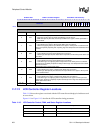
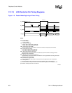
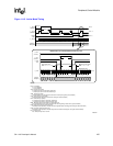
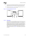
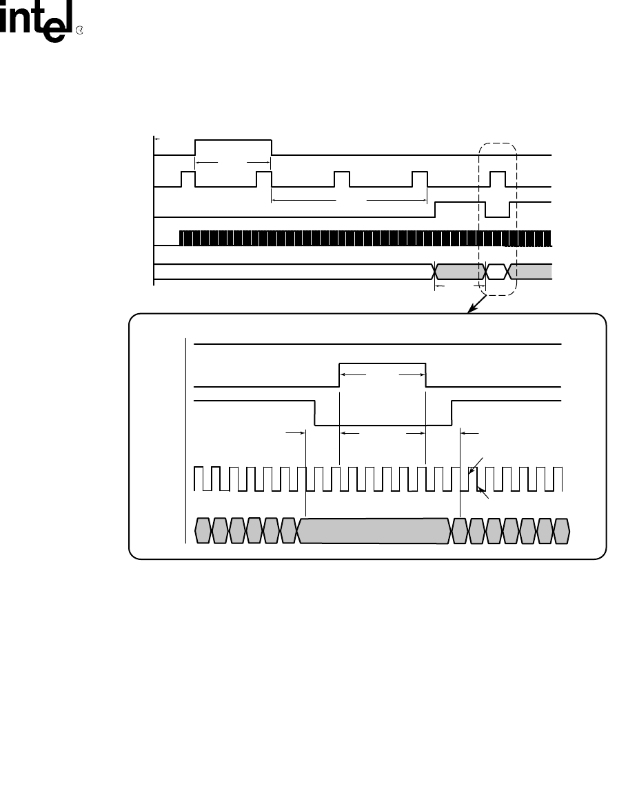
Figure 11-12. Active Mode Timing
A9002-01
L_FCLK
(VSYNC)
L_LCLK
(HSYNC)
L_BIAS
(OE)
*L_PCLK
LDD[7:0],
GPIO[9:2]
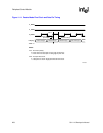
Notes:
LEN - LCD enable:
0 - LCD is disabled.
1 - LCD is enabled.
VSP - Vertical sync polarity:
0 - Vertical sync clock is active high, inactive low.
1 - Vertical sync clock is active low, inactive high.
VSW - Vertical sync width:
1 to 64 horizontal sync clock periods to assert the vertical sync signal (hsync transitions).
HSW - Horizontal sync pulse width:
2 to 65 pixel clock periods to assert the line clock (pixel clock transitions).
HSP - Horizontal sync polarity:
0 - Horizontal sync clock is active high, inactive low.
1 - Horizontal sync clock is active low, inactive high.
BFW - Beginning-of-frame horizontal sync clock wait count:
0 or 2 to 256 horizontal sync clock periods to wait at the beginning of each frame (hsync transitions).
BLW - Beginning-of-line pixel clock wait count:
2 to 256 pixel clock periods to wait after line clock negated before asserting pixel clocks (pixel clock transitions).
ELW - End-of-line pixel clock wait count:
2 to 256 pixel clock periods to wait after last pixel in line before asserting line clock (pixel clock transitions).
PPL - Pixels per line:
16 to 1024 pixels per line on screen
.
Line 1 Data
Line 0 Data
PPL = 16
VSP = 0
VSW = 0
BFW = 1
*NOTE: L_PCLK is not to scale here, please see detail below
LEN set to 1
HSP = 0
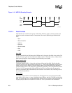
End of line wait =
ELW + 1 = 1 + 1 = 2
data driven here
data sampled here
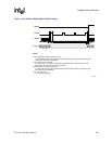
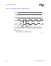
L_FCLK
(VSYNC)
L_LCLK
(HSYNC)
L_BIAS
(OE)
L_PCLK
LDD[7:0],
GPIO[9:2]
Beginning of line wait =
BLW + 1 = 1 + 1 = 2
ELW = 1
BLW = 1
OEP = 0
HSYNC PULSE WIDTH = HSW + 2 = 3 + 2 = 5
HSW = 3
TIMING DETAIL FOR THE BEGINNING AND END OF A LINE
pixels/line = PPL + 16 = 16 + 16 = 32
last pixel of the line (using PPL = 16)
pix 1
pix 0
pix 2
pix 3
pix 4
pix 5
pix 6
pix 25
pix 26
pix 27
pix 28
pix 29
pix 30
pix 31
PCP = 0