


232 SA-1110 Developer’s Manual
Peripheral Control Module
of LDD or the LCD controller’s ability to set and clear LDD; it only blocks the generation of the
interrupt request. This interrupt is particularly useful when the user needs to ensure the LCD has
been disabled and the current frame that is being output to the pins has completed, before entering
sleep mode. If the user disables the LCD, but does not need to enter sleep mode, this interrupt can
be masked using LDM.
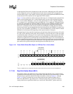
11.7.3.5 Base Address Update Interrupt Mask (BAM)
The base address update interrupt mask (BAM) bit is used to mask or enable interrupt requests that
are asserted at the beginning of each frame when the LCD’s base address pointer is transferred to
the current address pointer within the LCD’s DMA. When BAM=0, the interrupt is enabled, and
whenever the base address update (BAU) status bit within the LCD status register (LCSR) is set
(one) an interrupt request is made to the interrupt controller. When BAM=1, the interrupt is masked
and the state of the BAU status bit is ignored by the interrupt controller. Note that programming
BAM=1 does not affect the current state of BAU or the LCD controller’s ability to set and clear
BAU; it only blocks the generation of the interrupt request. Note that this interrupt mask is
particularly useful when the user wishes to enter idle mode to turn off the CPU and to display the
same image (the off-chip frame buffer data does not change). By masking the BAU interrupt, the
SA-1110 is not forced out of idle mode at the end of each frame.
11.7.3.6 Error Interrupt Mask (ERM)
The error interrupt mask (ERM) bit is used to mask or enable interrupt requests that are asserted
whenever a bus error or input/output FIFO over/underrun error occurs. When ERM=0, all error
interrupts are enabled, and whenever the bus error (BER) status bit or any of the input/output FIFO
over/underrun (IOL, IUL, IOU, IUU, OOL, OUL, OOU, OUU) status bits within the LCD status
register (LCSR) are set (one), an interrupt request is made to the interrupt controller. When
ERM=1, error interrupts are masked; the state of all of the error status bits (BER, IOL, IUL, IOU,
IUU, OOL, OUL, OOU, OUU) are ignored by the interrupt controller. Note that programming
ERM=1 does not affect the current state of these status bits or the LCD controller’s ability to set
and clear them; it only blocks the generation of the interrupt requests.
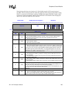
11.7.3.7 Passive/Active Display Select (PAS)
The passive/active display select (PAS) bit selects whether the LCD controller operates in passive
(STN) or active (TFT) display control mode. When PAS=0, passive or STN mode is selected, all
LCD data flow operates normally (including the use of the LCD’s dither logic), and all LCD
controller pin timing operates as described in the preceding sections.
When PAS=1, active or TFT mode is selected. For 4- and 8-bit per pixel modes, pixel data is
transferred via the DMA from off-chip memory to the input FIFO, is unpacked and used to select an
entry from the palette, just like passive mode. However, the value read from the palette bypasses the
LCD’s dither logic, and is sent directly to the output FIFO to be output on the LCD’s data pins. This
12-bit value output to the pins represents 4 bits of red, 4 bits of green, and 4 bits of blue data. For
12- and 16-bit pixel encoding mode, the pixel size within the frame buffer is increased to 16 bits.
Thus two 16-bit values are packed into each word in the frame buffer. Each 16-bit value is transferred
via the DMA from off-chip memory to the input FIFO. Unlike 4- and 8-bit per pixel modes, the 16-bit
value bypasses both the palette and the dither logic, and is placed directly in the output FIFO to be
output on the LCD’s data pins. Increasing the size of the pixel representation allows a total of 64K
colors to be generated. This 16-bit value output to the pins can be organized into one of three RGB
color formats: 6 bits of red, 5 bits of green, and 5 bits of blue data; 5 bits of red, 6 bits of green, and 5
bits of blue data; 5 bits of red, 5 bits of green, and 6 bits of blue data, as specified by the user. Note
that the pin timing of the LCD changes when active mode is selected. Timing of each pin is described