


414 SA-1110 Developer’s Manual
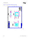
Boundary-Scan Test Interface
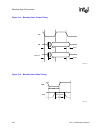
16.2 Reset
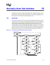
The boundary-scan interface includes a state-machine controller (the TAP controller). To force the
TAP controller into the correct state after power-up of the device, a reset pulse must be applied to
the nTRST pin. If the boundary-scan interface is to be used, then nTRST must be driven low, and
then high again. If the boundary-scan interface is not to be used, then the nTRST pin may be tied
permanently low. Note that a clock on TCK is not necessary to reset the device.
The action of reset (either a pulse or a DC level) is as follows:
• System mode is selected (the boundary-scan chain does NOT intercept any of the signals
passing between the pads and the core).
• IDcode mode is selected. If TCK is pulsed, the contents of the ID register will be clocked out
of TDO.
16.3 Pull-Up Resistors
The IEEE 1149.1 standard effectively requires that TDI, nTRST, and TMS should have internal
pull-up resistors. To minimize static current draw, nTRST has an internal pull-down resistor. These
pins can be left unconnected for normal operation and overdriven to use the JTAG features.
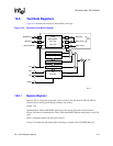
16.4 Instruction Register
The instruction register is 5 bits in length. There is no parity bit. The fixed value loaded into the
instruction register during the CAPTURE-IR controller state is: 00001.
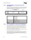
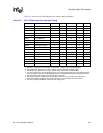
16.5 Public Instructions
The following public instructions are supported:
Instruction Binary Code
EXTEST 00000
SAMPLE/PRELOAD 00001
CLAMP 00100
HIGHZ 00101
IDCODE 00110
BYPASS 11111
Private 00010, 00011, 00111, 01000-01111, 10000-11110
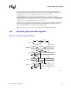
In the descriptions that follow, TDI and TMS are sampled on the rising edge of TCK, and all output
transitions on TDO occur as a result of the falling edge of TCK.