


SA-1110 Developer’s Manual 239
Peripheral Control Module
it is split into two panels. LPP is a 10-bit value that represents between 1 and 1024 lines per screen.
The user should program LPP with the desired height of the display minus one. LPP is used to count
the correct number of line clocks that must occur before the frame clock can be pulsed.
The LCD’s DMA may overshoot the end of frame buffer by one burst cycle (4-word read). The LCD’s
DMA reads these extra values but they are flushed from the input FIFO each time the frame clock is
pulsed. The user must ensure that the four words immediately following the end of the frame buffer
reside in legal memory space (do not cause a bus error if read). Because the LCD does not alter this
memory (only reads are performed), these locations can be used for data storage unrelated to the LCD.
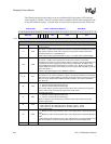
11.7.5.2 Vertical Sync Pulse Width (VSW)
The 6-bit vertical sync pulse width (VSW) field is used to specify the pulse width of the vertical
synchronization pulse in active mode, or is used to add extra “dummy” line clock waitstates
between the end and beginning of frame in passive mode.
In active mode (PAS=1), L_FCLK is used to generate the vertical sync signal and is asserted each
time the last line or row of pixels for a frame is output to the display and a programmable number
of line clock waitstates have elapsed as specified by ELW. When L_FCLK is asserted, the value in
VSW is transferred to a 6-bit down counter, which uses the line clock frequency to decrement.
When the counter reaches zero, L_FCLK is negated. VSW can be programmed to generate a
vertical sync pulse width ranging from 1 to 64 line clock periods. The user should program VSW
with the desired number of line clocks minus one. Note that the line clock does not transition
during generation of the vertical sync pulse. Also note that the polarity (active and inactive state) of
the L_FCLK pin is programmed using the frame clock polarity (FCP) bit in LCCR3.
In passive mode (PAS=0), VSW does not affect the timing of the L_FCLK pin, but rather can be
used to add extra line clock waitstates between the end of each frame and the beginning of the next
frame. When the last line clock of a frame is negated, the value in VSW is transferred to a 6-bit
down counter that uses the line clock frequency to decrement. When the counter reaches zero, the
next frame is permitted to begin. VSW can be programmed to generate from 1 to 64 dummy line
clock periods between each frame in passive mode. The user should program VSW properly to
ensure that enough waitstates occur between frames such that the LCD’s DMA is able to fully load
the on-chip palette, as well as allowing a sufficient number of encoded pixel values to be input
from the frame buffer, to be processed by the dither logic, and placed in the output FIFO, ready to
be output to the LCD’s data pins. The number of waitstates required is system dependent. The
factors that determine the number of waitstates include: palette buffer size (32 or 512 bytes),
memory system speed (number of waitstates, burst speed, number of beats), and what value is
programmed in the palette DMA request delay (PDD) bit-field in LCCR0. Note that the line clock
pin does transition during the insertion of the line clock waitstate periods.
VSW does not affect generation of the frame clock signal in passive mode. Passive LCD displays
require that the frame clock is active on the rising edge of the first line clock pulse of each frame,
with adequate setup and hold time. To meet this requirement, the LCD controller’s frame clock pin
is asserted on the rising edge of the first pixel clock for each frame. The frame clock remains
asserted for the remainder of the first line as pixels are output to the display and it is then negated
on the rising edge of the first pixel clock of the second line of each frame.
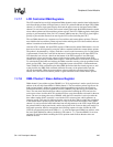
11.7.5.3 End-of-Frame Line Clock Wait Count (EFW)
The 8-bit end-of-frame line clock wait count (EFW) field is used in active mode (PAS=1) to
specify the number of line clocks to insert at the end of each frame. Once a complete frame of
pixels is transmitted to the LCD display, the value in EFW is used to count the number of line clock
periods to wait. After the count has elapsed, the VSYNC (L_FCLK) signal is pulsed. EFW