24 SA-1110 Developer’s Manual
Introduction
1.2 Overview
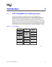
The SA-1110 is a general-purpose, 32-bit RISC microprocessor with a 16 Kbyte instruction cache, an
8 Kbyte write-back data cache, a minicache, a write buffer, a read buffer, and a memory management
unit (MMU) combined in a single chip. The SA-1110 is software compatible with the ARM
*
V4
architecture processor family and can be used with ARM
*
support chips such as I/O, memory, and
video. The core of the SA-1110 is derived from the core of the Intel
®
StrongARM SA-110
Microprocessor (SA-110), with the following changes:
• Reduction in size of the data cache from 16 Kbyte to 8 Kbyte
• Addition of a 512-byte mini data cache that allocates data based on MMU settings
• Addition of debug support in the form of address and data breakpoints
• Addition of a four-entry read buffer to facilitate software-controlled data prefetching
• Addition of vector address adjust capability
• Addition of a process ID register
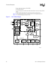
The logic outside the core and caches is grouped into the following three modules:
• Memory and PCMCIA control module (MPCM)
– Memory interface supporting ROM, Synchronous Mask ROM (SMROM), Flash, DRAM,
SDRAM, SRAM, SRAM-like variable latency I/O, and PCMCIA control signals
• System control module (SCM)
– Twenty-eight general-purpose interruptible I/O ports
– Real-time clock, watchdog, and interval timers
– Power management controller
– Interrupt controller
– Reset controller
– Two on-chip oscillators for connection to 3.686 MHz and 32.768 kHz crystals
• Peripheral control module (PCM)
– Six-channel DMA controller
– Gray/color, active/passive LCD controller
– 16550-compatible UART
– IrDA serial port (115 Kbps, 4 Mbps)
– Synchronous serial port (UCB1100, UCB1200, SPI, TI, µWire)
– Universal serial bus (USB) device controller
The instruction set comprises eight basic instruction types:
• Two make use of on-chip arithmetic logic unit, barrel shifter, and multiplier to perform high-speed
operations on data in a bank of 16 logical registers (31 physical registers), each 32 bits wide.
• Three classes of instructions control data transfer between memory and the registers: one
optimized for flexibility of addressing, one for rapid context switching, and one for swapping data.
• Two instructions control the flow and privilege level of execution.
• One class is used to access the privileged state of the CPU.


