


260 SA-1110 Developer’s Manual
Peripheral Control Module
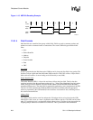
Packets are assembled into groups to produce frames. Frames (or transactions) fall into four
groups:
• Bulk
• Control
• Interrupt (not supported by SA-1110 UDC)
• Isochronous (not supported by SA-1110 UDC)
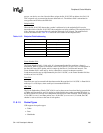
Endpoint 0, by default, is used only to communicate “Control” frames to configure the SA-1110
UDC after it is reset or physically connected to an active USB Host or hub. Endpoint 0’s responsi-
bilities include:
• Connection
• Address Assignment
• Endpoint Configuration
• Bus Enumeration
• Disconnect
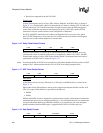
Endpoint 1 is used for “Bulk OUT” Data frames, i.e., SA-1110 UDC receives data from the Host;
Endpoint 2 is used for “Bulk IN” Data frames, i.e., SA-1110 UDC transmits data to the Host.
The SA-1110 UDC uses two separate FIFOs to buffer “Bulk OUT” Data frames received by
Endpoint 1 from the Host and buffer “Bulk IN” Data frames transmitted from Endpoint 2 to the
Host. The Receive Data FIFO is 20-entry x 8-bit and the Transmit Data FIFO is 16-entry x 8-bit.
Both FIFOs can be filled or emptied either by the DMA or the CPU, with service requests being
signalled when either FIFO is half-full or empty. Interrupts are signalled when the Receive Data
FIFO experiences an overrun and/or when the Transmit Data FIFO experiences an underrun.
A single Control FIFO is used to buffer Control frames either received by Endpoint 0 from the
Host or transmitted from Endpoint 0 to the Host. The Control FIFO is 8-entry x 8-bit. The Control
FIFO can be read or written only by the CPU (not DMA).
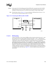
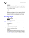
UDC+ and UDC- are external SA-1110 UDC pins that are to be connected to the UDC+ and UDC-
wires in the USB cable. The USB protocol uses differential signalling between these pins to
provide half-duplex data transmission. A 1.5-Kohm pull-up resistor as shown in Figure 11-14 is
required to be connected to the USB cable’s D+ wire to pull the UDC+ pin high when it is not
driven. This signifies that the SA-1110 UDC is a 12-Mbps device, and it specifies the correct
polarity for data transmission. Differential signalling between UDC+ and UDC- allows multiple
states to be transmitted on the USB bus. These states are combined to transmit data as well as
encode various bus conditions. The Bus conditions include:
• Idle
• Resume
• Start Of Packet
• End Of Packet
• Disconnect
• Connect
• Reset