


74 SA-1110 Developer’s Manual
System Control Module
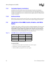
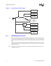
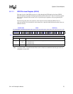
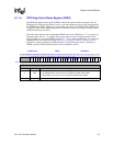
Figure 9-1. General-Purpose I/O Block Diagram
9.1.1 GPIO Register Definitions
There are a total of eight registers within the GPIO control block: one is used to monitor pin state;
two are used to control pin state; one is used to control pin direction; two are used to specify a pin’s
edge type that should be detected; and one is used to flag when specified edge types are detected on
pins.
The last register indicates whether a pin is used as normal GPIO or whether it is taken over by the
alternate function. The values in all other GPIO registers are unknown following reset and must be
initialized by software.
Note: A question mark (?) signifies that the Reset value of that bit is undefined when the processor has
completed its reset cycle.
Edge
Detect
GPIO Pin
Pin Direction
Register
Pin Set and
Clear Registers
Alternate Function
(Output)
Alternate Function
(Input)
Edge Detect
Status Register
Pin-Level
Register
0
1
Alternate Function
Register
Rising Edge Detect
Enable Register
Falling Edge Detect
Enable Register