


86 SA-1110 Developer’s Manual
System Control Module
9.2.1.2 Interrupt Controller IRQ Pending Register (ICIP) and FIQ Pending
Register (ICFP)
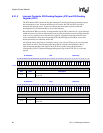
The ICIP and the ICFP contain one flag per interrupt (32 total) that indicates an interrupt request
has been made by a unit. Inside the interrupt service routine, the ICIP and ICFP are read to
determine the interrupt source. In general, software then reads status registers within the
interrupting device to determine how to service the interrupt.
Bits within the ICPR are read only, and represent the logical OR of status bits for a given interrupt
within the source unit. Once an interrupt has been serviced, the handler clears the pending interrupt
at the source by writing a one to the necessary status bit. Clearing the interrupt status bit at the
source automatically clears the corresponding ICIP and ICFP flag provided there are no other
interrupt status bits set within the source unit.
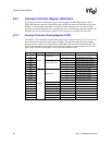
All interrupt source status bits are cleared by writing a one to them. Writing a zero to an interrupt
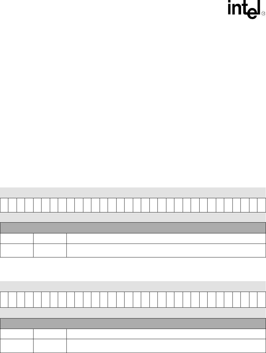
status bit has no effect. The following table shows the bit locations corresponding to the 32
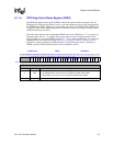
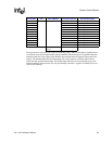
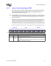
separate interrupt pending status flags in the ICIP. The next table shows the bit locations
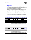
corresponding to the 32 separate interrupt pending status flags in the ICFP. This is a read-only
register.
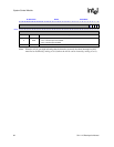
0h 9005 0000 ICIP Read-Only
31 30 29 28 27 26 25 24 23 22 21 20 19 18 17 16 15 14 13 12 11 10 9 8 7 6 5 4 3 2 1 0
IP31
IP30
IP29
IP28
IP27
IP26
IP25
IP24
IP23
IP22
IP21
IP20
IP19
IP18
IP17
IP16
IP15
IP14
IP13
IP12
IP11
IP10
IP9
IP8
IP7
IP6
IP5
IP4
IP3
IP2
IP1
IP0
Reset 0 0 0 0 0 0 0 0 0 0 0 0 0 0 0 0 0 0 0 0 0 0 0 0 0 0 0 0 0 0 0 0
Bits Name Description
31..0 —
These flags reflect the OR of the reset state of the individual interrupt status bits at the
source unit.
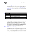
0h 9005 0010 ICFP Read-Only
31 30 29 28 27 26 25 24 23 22 21 20 19 18 17 16 15 14 13 12 11 10 9 8 7 6 5 4 3 2 1 0
FP31
FP30
FP29
FP28
FP27
FP26
FP25
FP24
FP23
FP22
FP21
FP20
FP19
FP18
FP17
FP16
FP15
FP14
FP13
FP12
FP11
FP10
FP9
FP8
FP7
FP6
FP5
FP4
FP3
FP2
FP1
FP0
Bits Name Description
31..0 —
These flags reflect the OR of the reset state of the individual interrupt status bits at the
source unit.