


SA-1110 Developer’s Manual 333
Peripheral Control Module
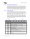
11.11.5.5 Transmit FIFO Interrupt Enable (TIE)
The transmit FIFO interrupt enable (TIE) bit is used to mask or enable the transmit FIFO service
request interrupt. When TIE=0, the interrupt is masked and the state of the transmit FIFO service
request (TFS) bit is ignored by the interrupt controller. When TIE=1, the interrupt is enabled, and
whenever TFS is set (one), an interrupt request is made to the interrupt controller. Note that
programming TIE=0 does not affect the current state of TFS nor the transmit FIFO logic’s ability to
set and clear TFS; it only blocks the generation of the interrupt request. Also note that TIE does
not affect generation of the transmit FIFO DMA request that is asserted whenever TFS=1.
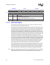
11.11.5.6 Loopback Mode (LBM)
The loopback mode (LBM) bit is used to enable and disable the ability of the UART transmit and
receive logic to communicate. When LBM=0, the UART operates normally. The transmit and receive
data paths are independent and communicate via their respective pins. When LBM=1, the output of
the transmit serial shifter is directly connected to the input of the receive serial shifter internally, and
control of the TXD3 and RXD3 pins is given to the peripheral pin control (PPC) unit.
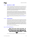
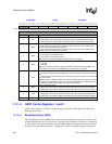
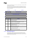
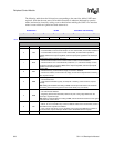
The following table shows the bit location of the bits within UART control register 3. RXE and
TXE are the only control bits that are reset to a known state to ensure the UART is disabled
following a reset of the SA-1110. The reset state of all other control bits is unknown (indicated by
question marks) and must be initialized before enabling the UART. Note that UTCR3 is the only
control register that may be written while the UART is enabled. Also note that writes to reserved
bits are ignored and reads return zeros.
0h 8005 000C UTCR3 Read/Write
7 6 5 4 3 2 1 0
Reserved LBM TIE RIE BRK TXE
RXE
Reset
0 0 ? ? ? ? 0 0
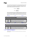
(Sheet 1 of 2)
Bits Name Description
0RXE
Receiver enable.
0 – UART receive operation disabled; PPC is given control of RXD3.
1 – UART receive operation enabled.
1TXE
Transmitter enable.
0 – UART transmit operation disabled; PPC is given control of TXD3.
1 – UART transmit operation enabled.
2BRK
Break.
0 – UART in normal operation.
1 – Force TXD3 low (all bits in the frame are a zero) to generate a break.
3RIE
Receive FIFO interrupt enable.
0 – Receive FIFO one- to two-thirds full (or more) and receiver idle conditions do not
generate an interrupt (RFS and RID bit ignored).
1 – Receive FIFO one- to two-thirds full (or more) and receiver idle conditions generate an
interrupt (state of RFS and RID sent to interrupt controller).
4TIE
Transmit FIFO interrupt enable.
0 –Transmit FIFO half-full or less condition does not generate an interrupt (TFS bit
ignored).
1 – Transmit FIFO half-full or less condition generates an interrupt (state of TFS sent to
interrupt controller).